
RCA Studio II 'Tester 1' Test Cartridge
There are only a handful of known cartridges for the RCA Studio II game console, but there have been rumors of a few more.
The last couple years have been particularly awesome for collectors of this system.
Only seen a couple of times in the wild years ago, many thought it was only a rumor, the elusive 'Bingo' cartridge appeared on eBay.
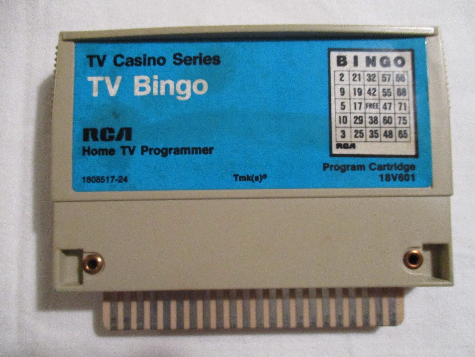
This was dumped and added to the multicart a few of us had been working on.
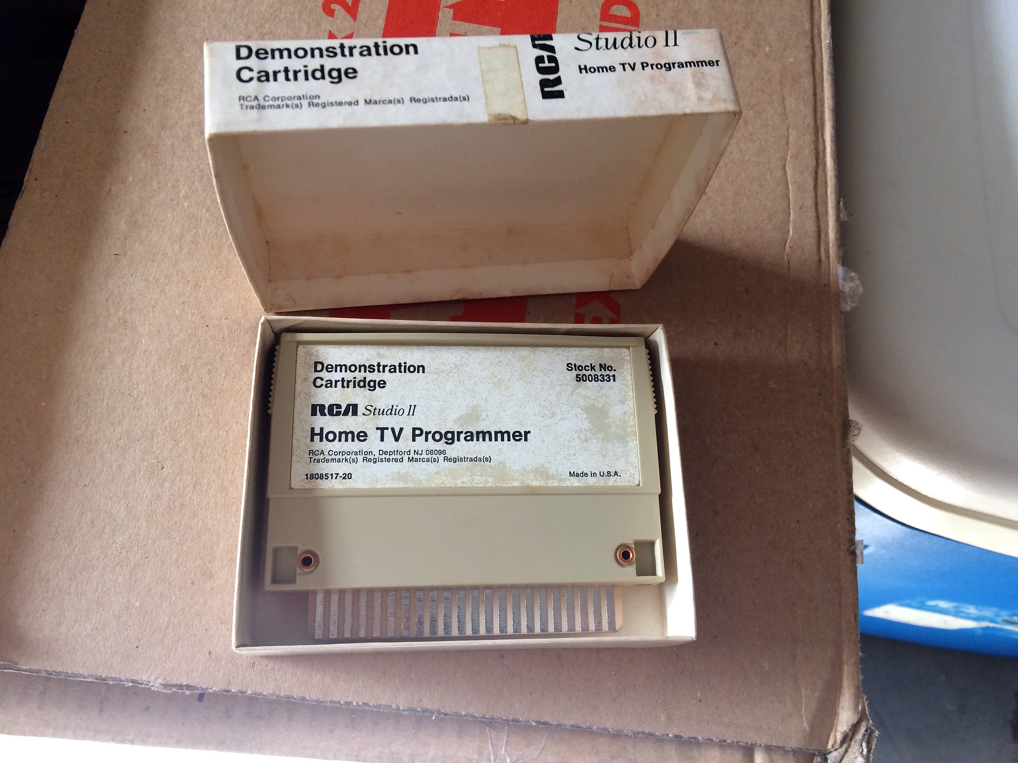
About a year later, the RCA demonstration cartridge appeared on eBay. It too was dumped and added to the multicart.
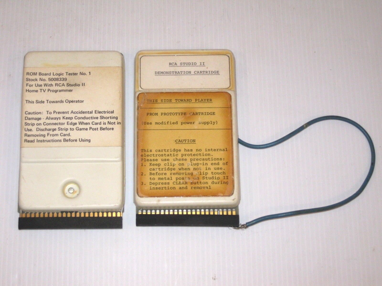
The only other cartridge that was known to exist was the 'Tester 1' cartridge used by the factory and a few authorized repair shops back when the Studio II was active in 1977-1978.
In 2018, one finally showed up on eBay.
I am fortunate to know who the lucky new owner is. They don't want to be identified, and I will not tell.
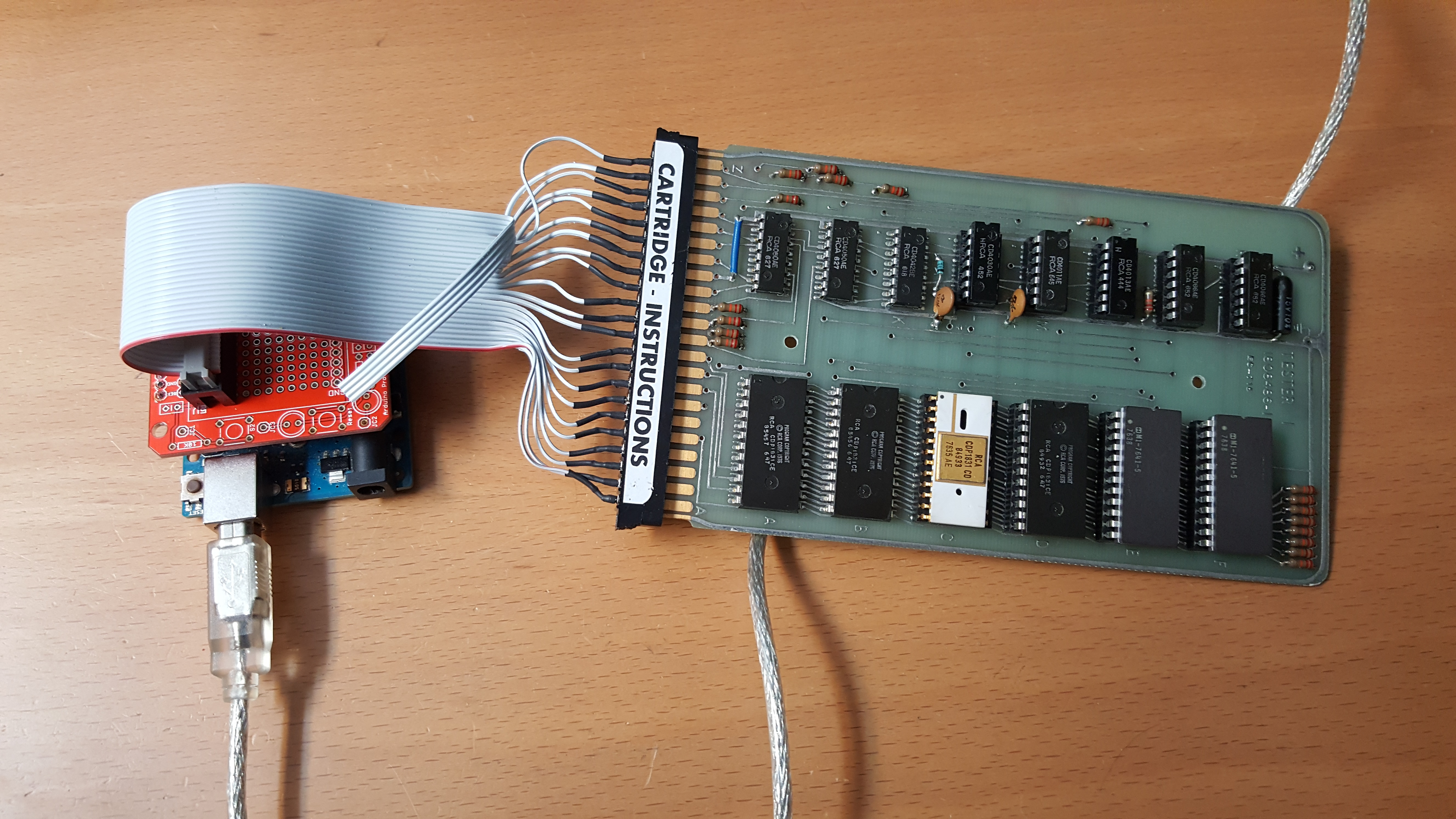
The new owner agreed to dump the ROM but didn't want to ship their new (expensive!) cartridge to me, so I sent my dumper to them with instructions.
The hope was to add this code to the multicart along with the others.
The cartridge dumped successfully. I tested the dump in the awesome Emma 02 1802 emulator (http://www.emma02.hobby-site.com). It would not run.
I am friends with the developer of the Emma 02 emulator. We have worked together on a few projects before including, the COMX-35 SuperBoard (http://www.comx35.com/superboard.html).
He was able to get the code running in his emulator, but it indicated each test had errors. Going through the code, he noticed that jumps were bring made outside of the normal Studio II memory map.
With a few more tweaks he had the 'Tester 1' code running. We both agreed that there was something else going on inside the real cartridge.
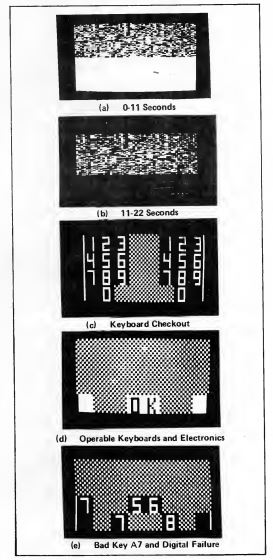
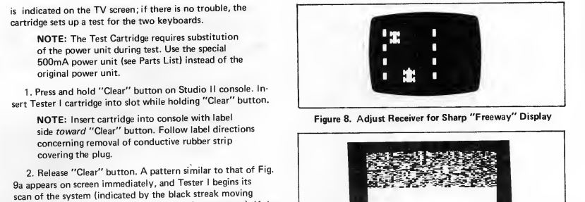
From the Studio II service manual, here is what the tests look like when running.
As a clue, the RCA Studio II Service manual indicates that a larger, more powerful power supply must be swapped for the one shipped with the console.
Here is a link to the Studio II Service Manual.
/RCA_Tester1/RCA_Studio_II_Service_Manual.pdf
This suggested that there was more than ROMs inside the cartridge.
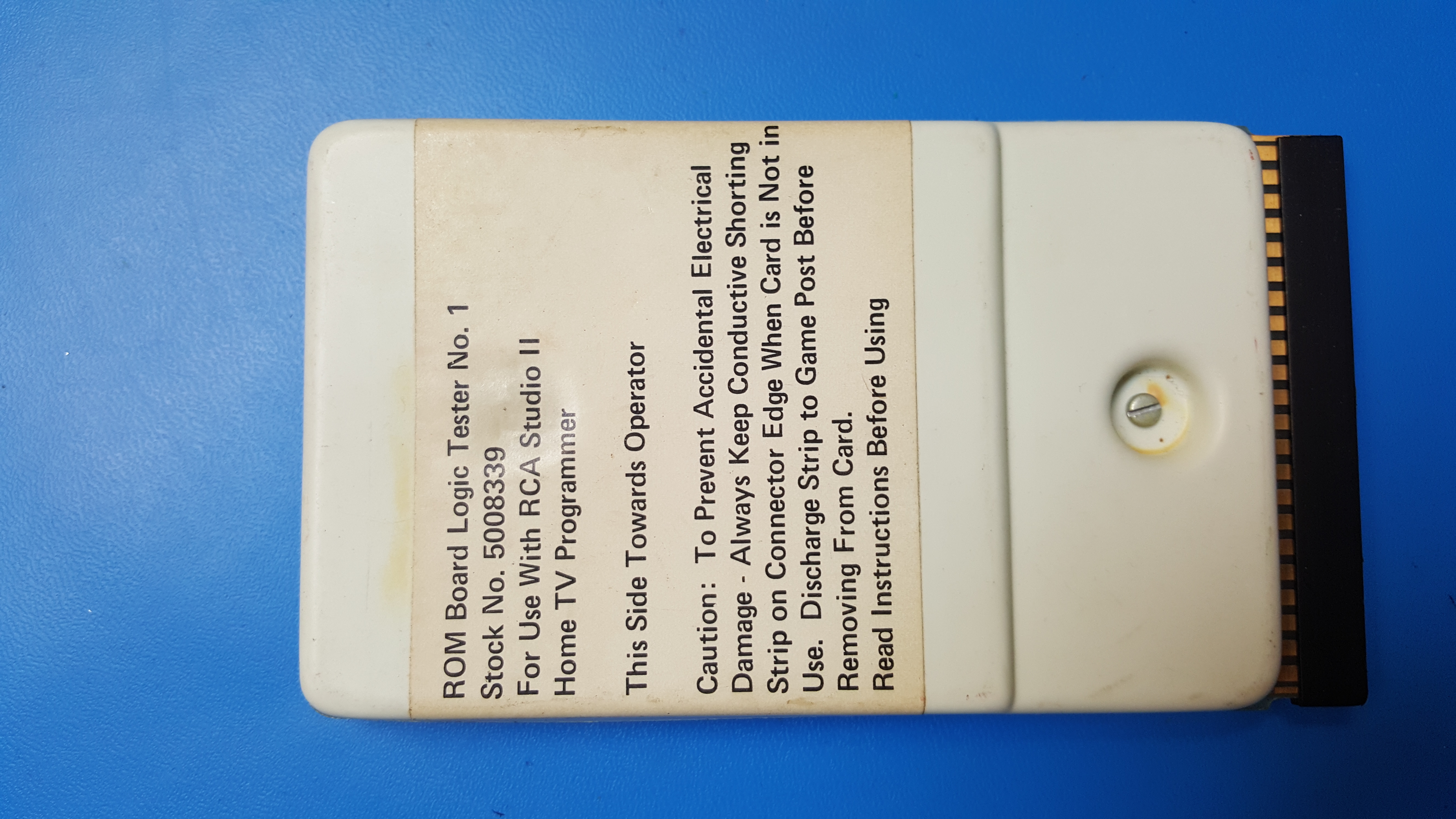
I asked the owner, with fingers crossed, if they would be willing to remove the cover and take some pictures for me so I could see and maybe trace out the circuit. They agreed and a nice collection of pictures was made available.
There was a lot more going on inside the cartridge than I thought.
I began attempting to trace out the circuit. I loaded a front and back image of the board into Photoshop and made an 'X-ray' of the PCB. The two pictures were at slightly different angles and had different sizes. Here is the image I created, with signal names on the cartridge fingers:
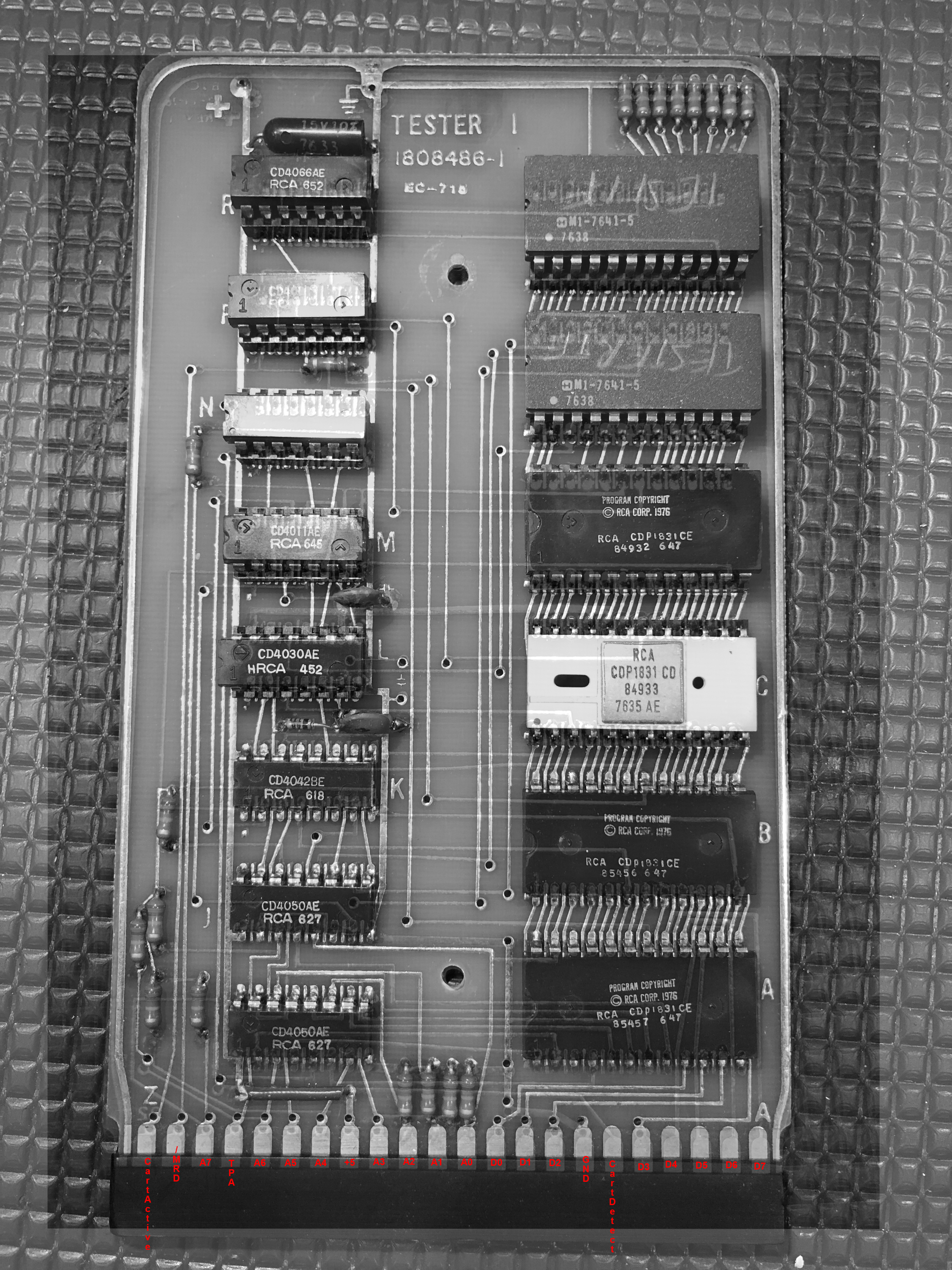
Even with the x-ray image, there were still some traces I couldn't figure out. Some of the circuits didn't make sense, such as how address line 5 was routed.
I put the project aside for a bit.
I figured it couldn't hurt, so I asked the owner to reconsider allowing me to borrow the cartridge for a couple days.
To my shock, and delight, they agreed!
They shipped it a few days later. It arrived in excellent shape.
The cover is usually held in place by two screws. The owner had removed them to take the pictures for me, so I put them aside.
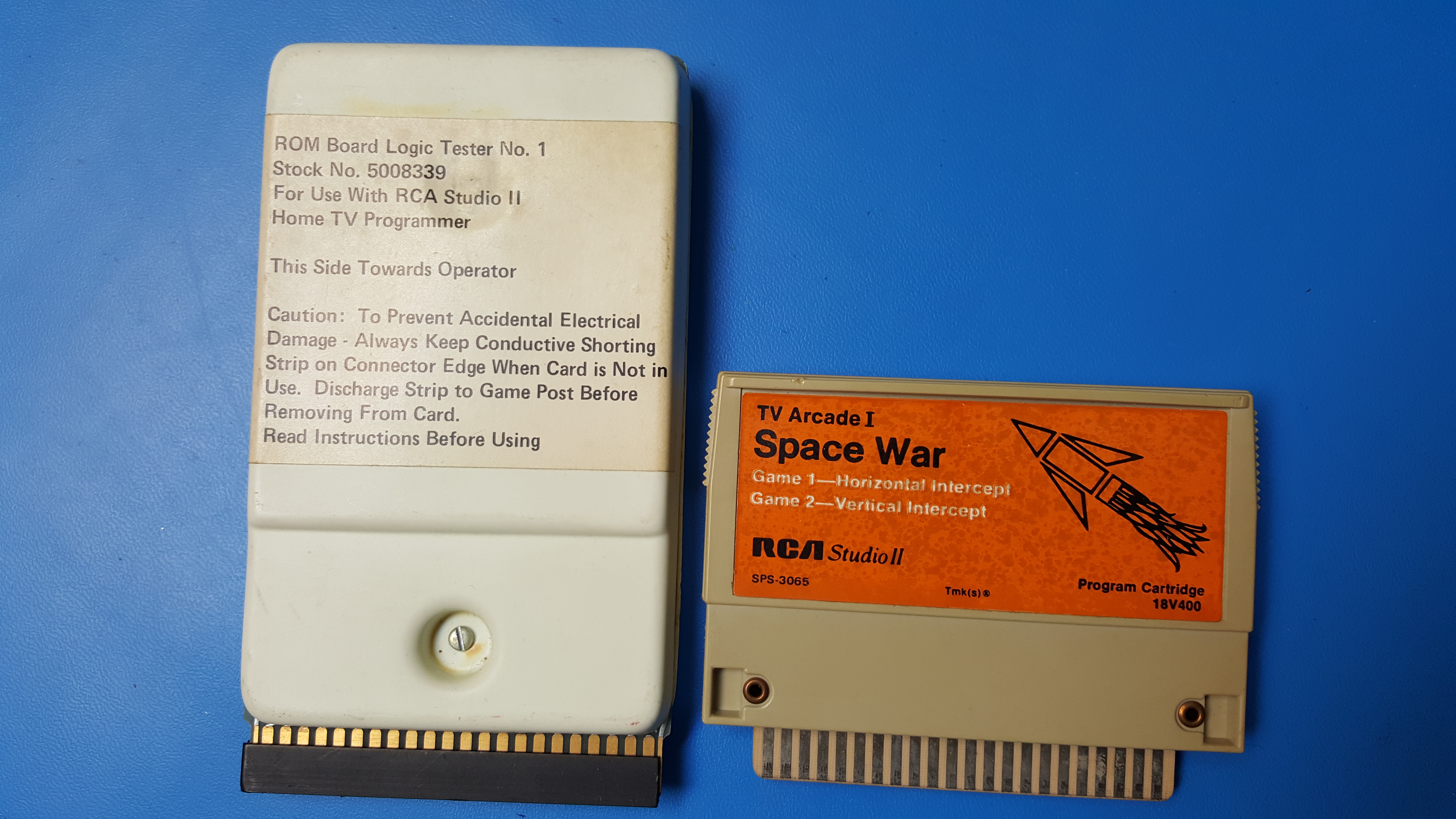
For comparison, here is a picture of the Tester 1 cartridge and a normal Studio II cartridge.
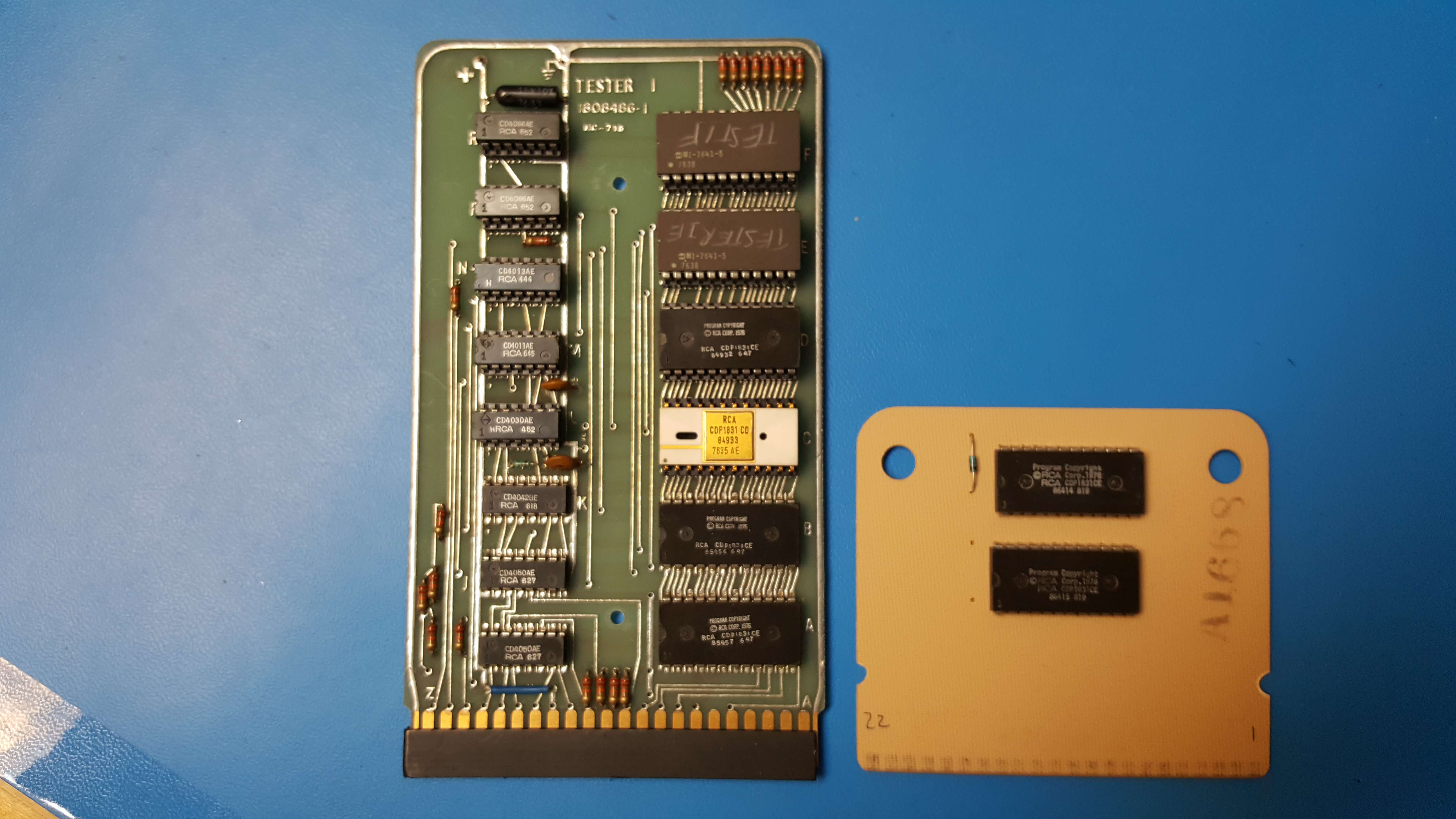
Comparison of the PCB size difference.
I started tracing out the circuit with a pencil and paper. The results of this were not pretty but I did have a complete set of connections. I copied the notes I had made and retraced the circuit to make sure I didn't miss anything.
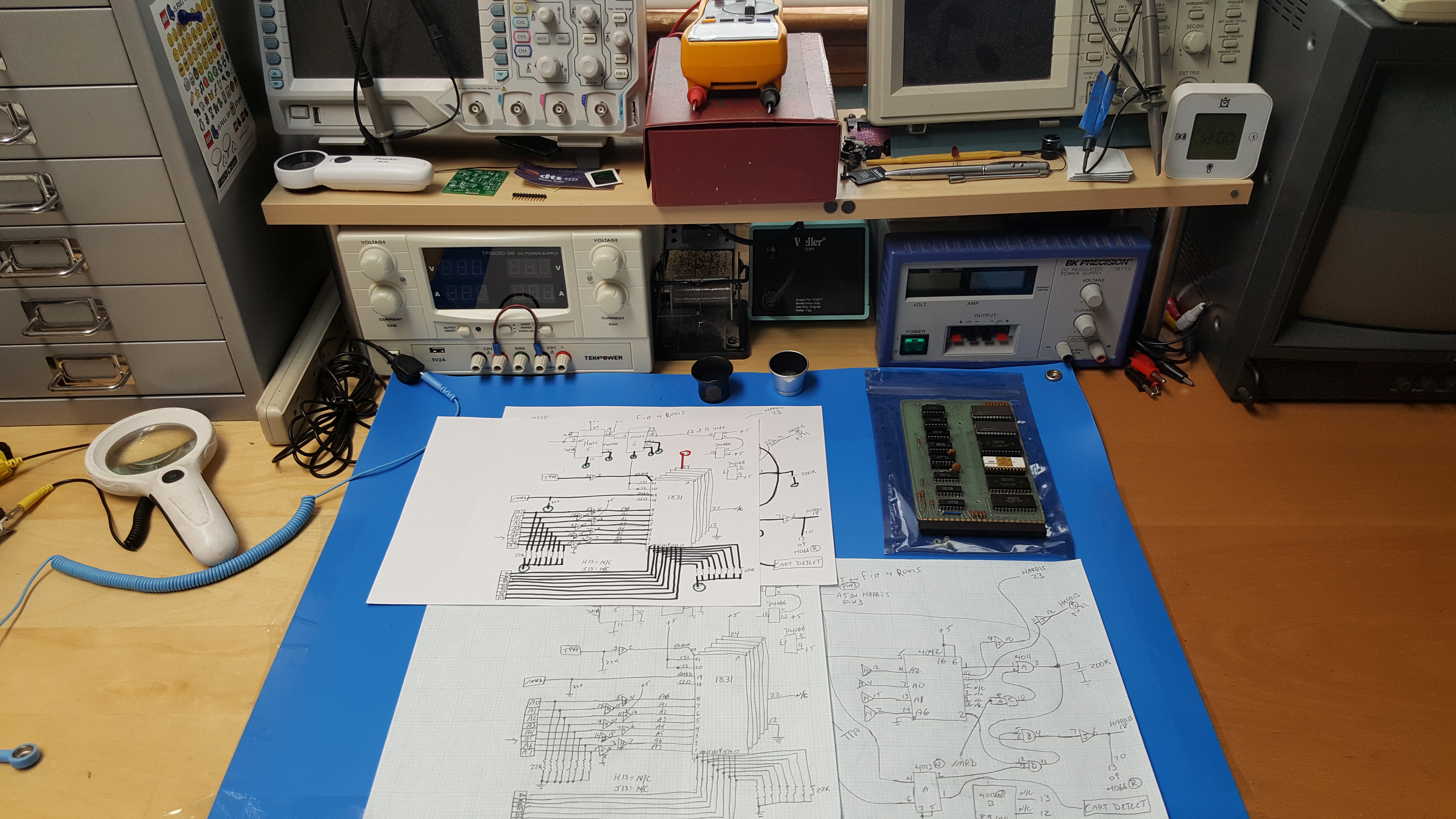
From this I created a complete formal schematic. It spanned two 'B' size pages (11" x 17"). I finalized the documentation with a few pages of notes.
You can download the schematic I made here:
/RCA_Tester1/Tester1_Schematic.pdf
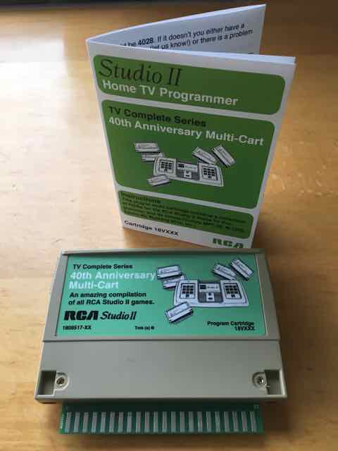
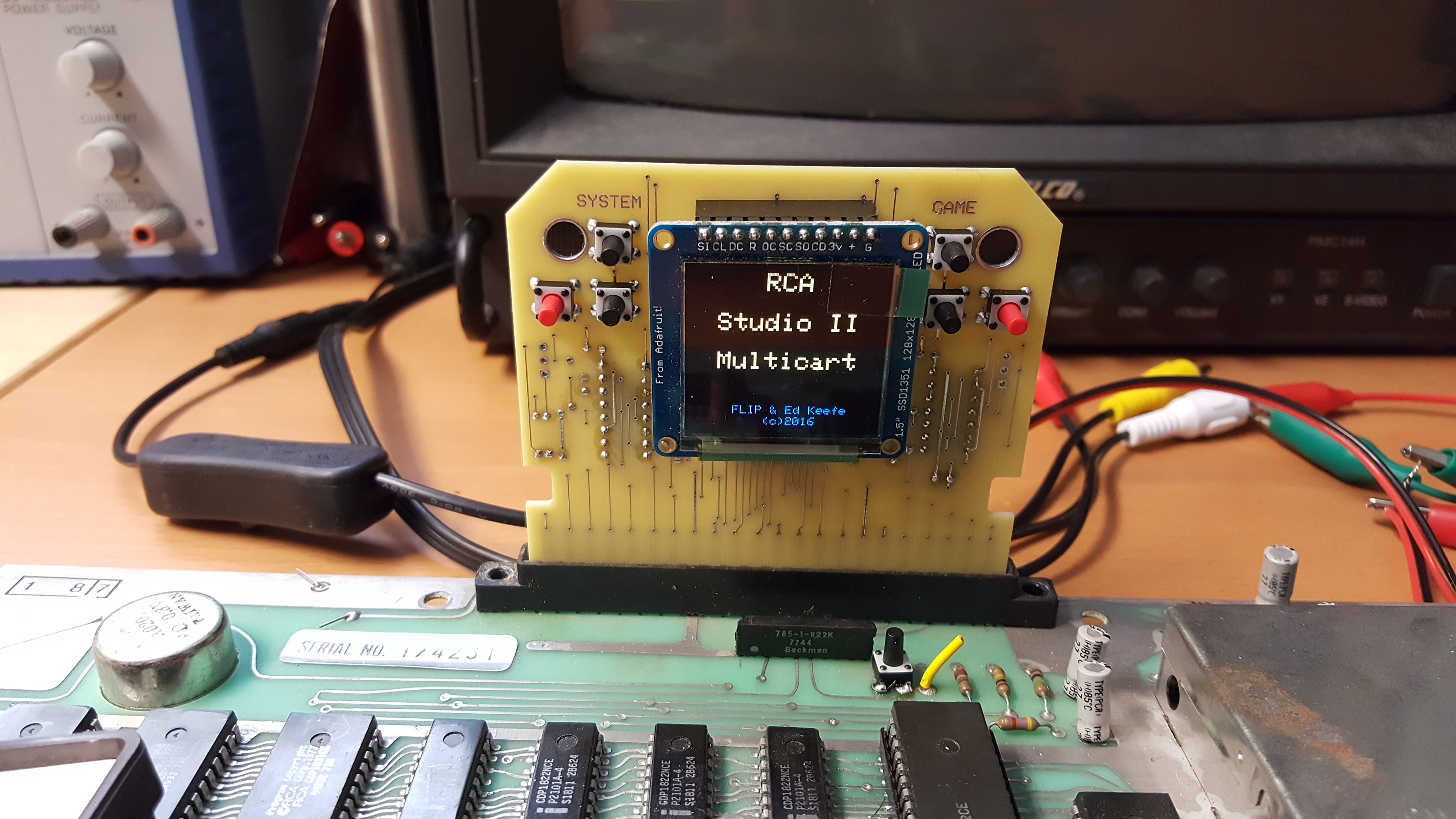
Unfortunately, the way the hardware manipulates memory in the Studio II, makes the Tester 1 code incompatible with the multicart. I've tested the code in both the public multicart, seen above, and the one I built personally, with no luck.
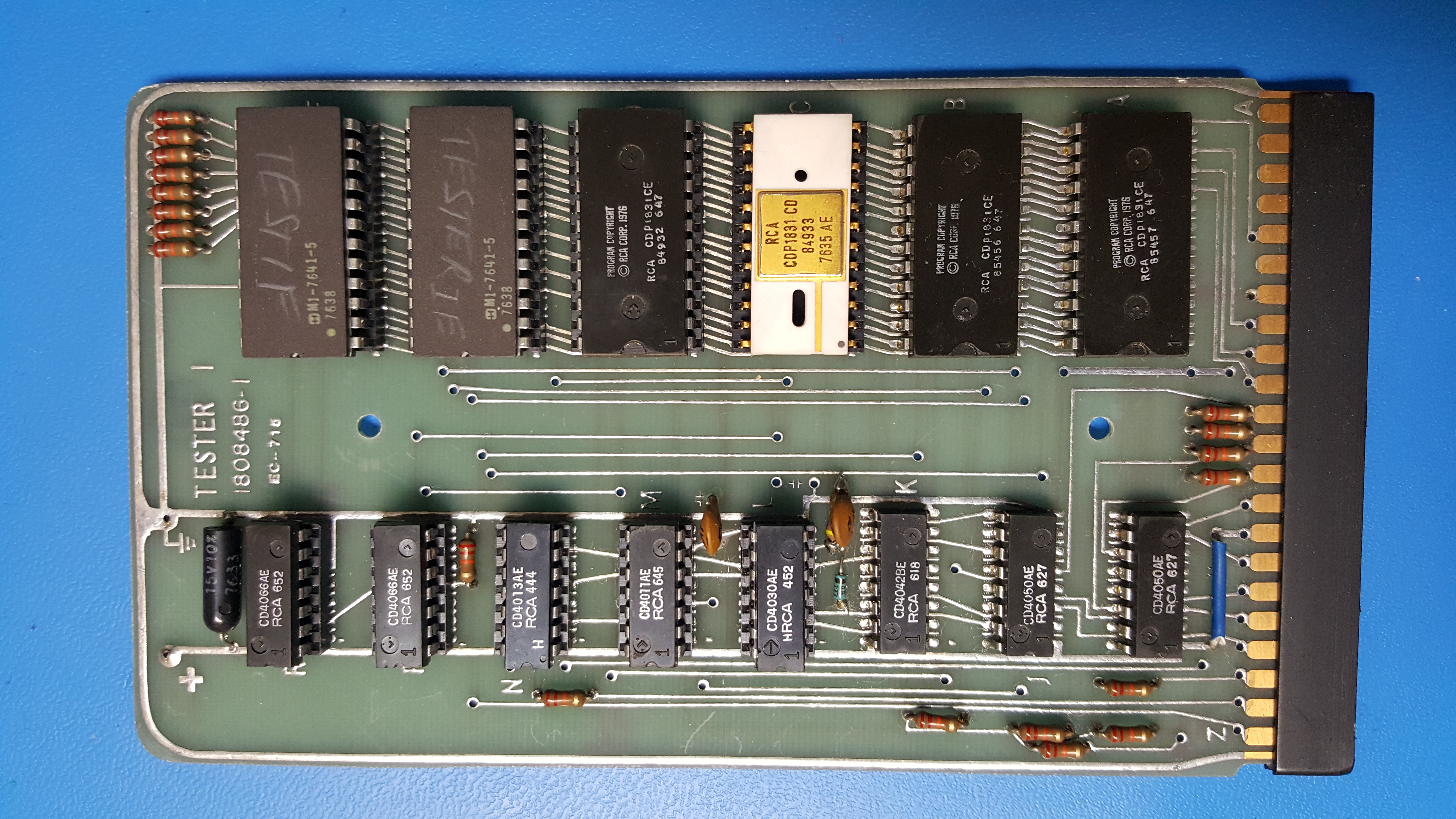
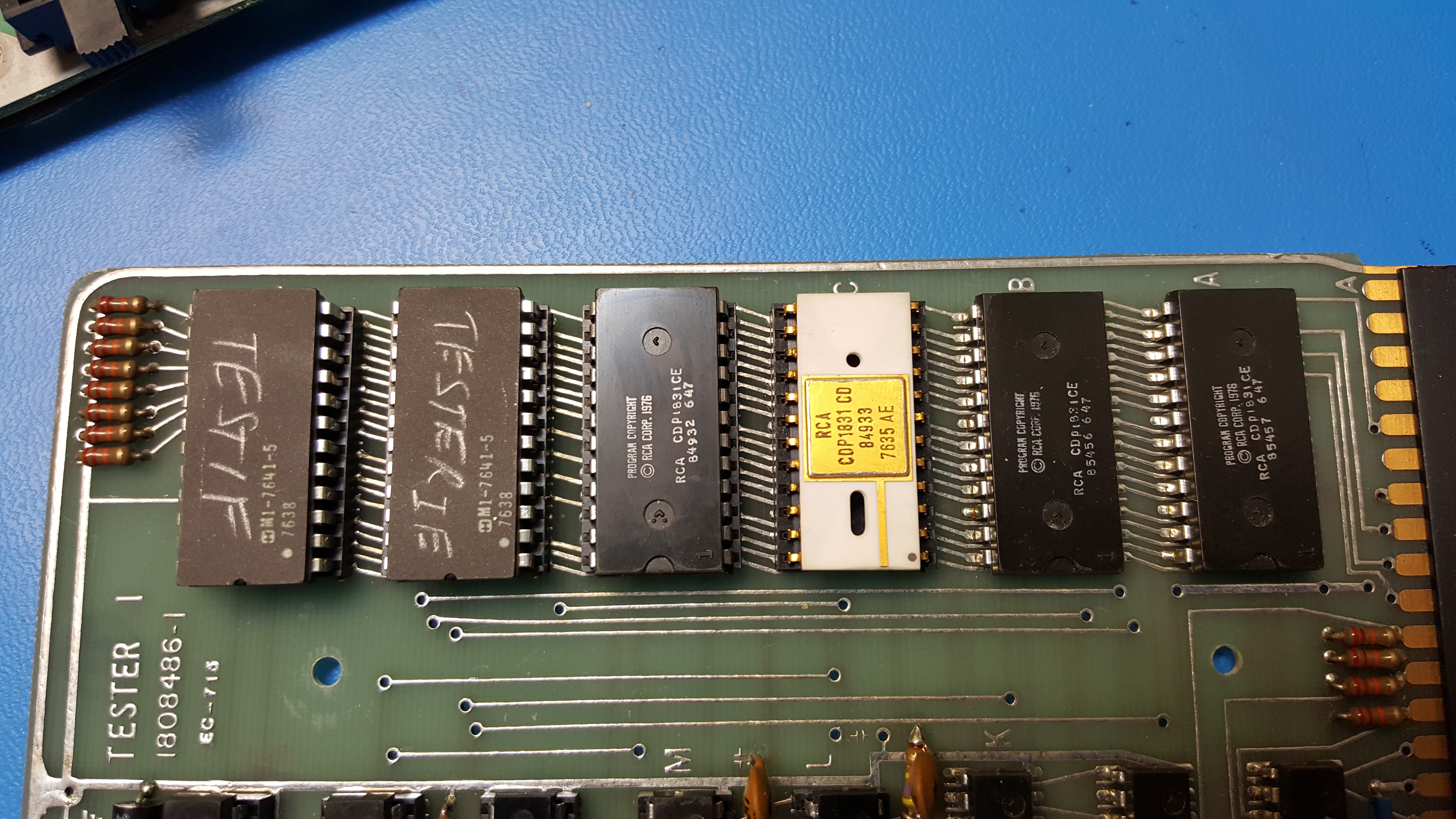
Since I had already dumped the contents of the two 'Tester 1' ROMs, I turned my attention to the four other ROMs. I noticed they each had a unique number on them under the part numbers. The four ROMs are CDP1831 which are factory mask programmed with a 512 byte program each. I knew these markings indicate the firmware version.
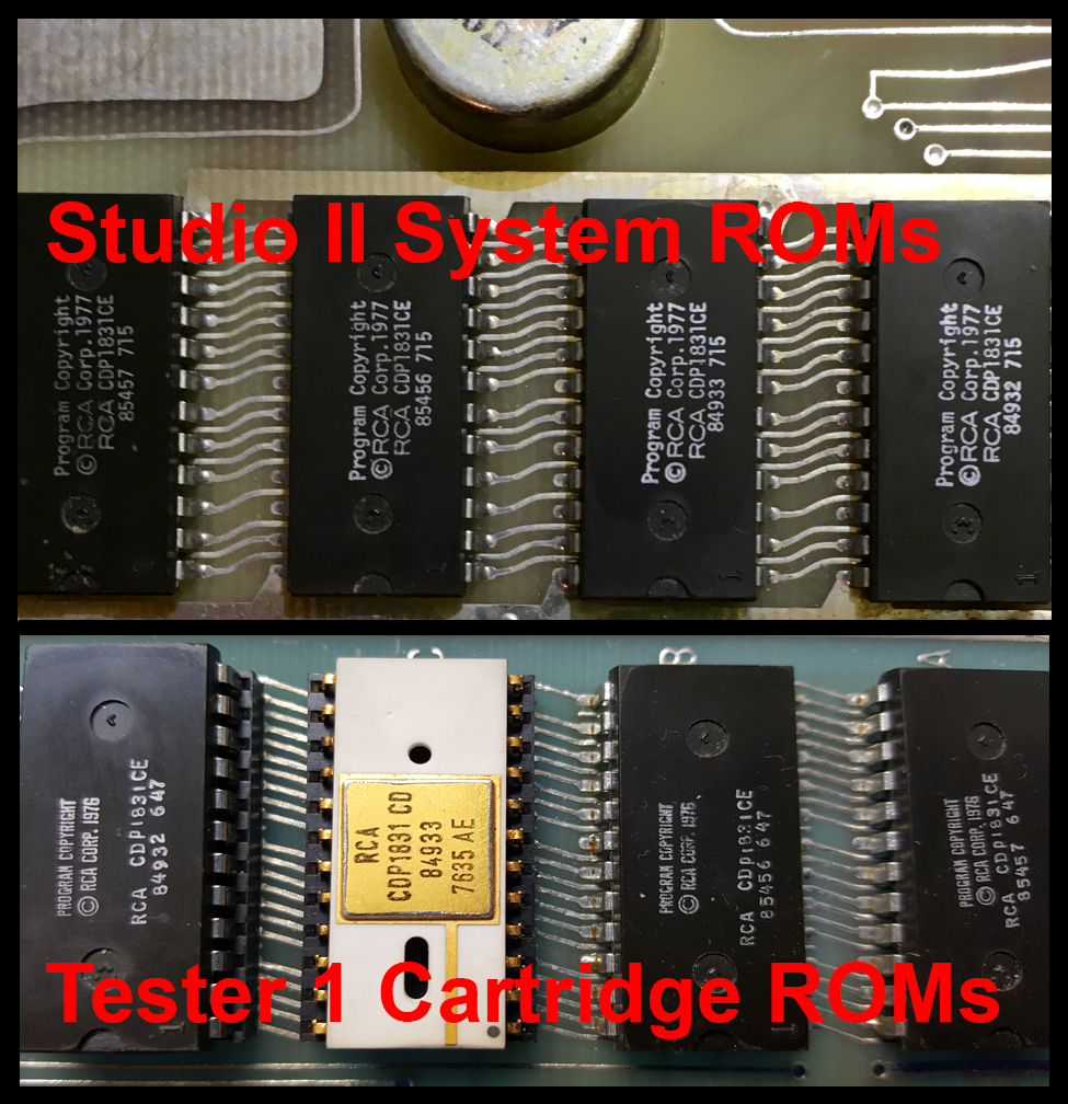
I recalled seeing these numbers somewhere else and since the cartridge's purpose was to test Studio IIs after manufacture or repair, I found one of my torn apart Studio II PCBs and compared the ROMs on it with the cartridge ROMs. The firmware numbers matched the four Studio II ROMs.
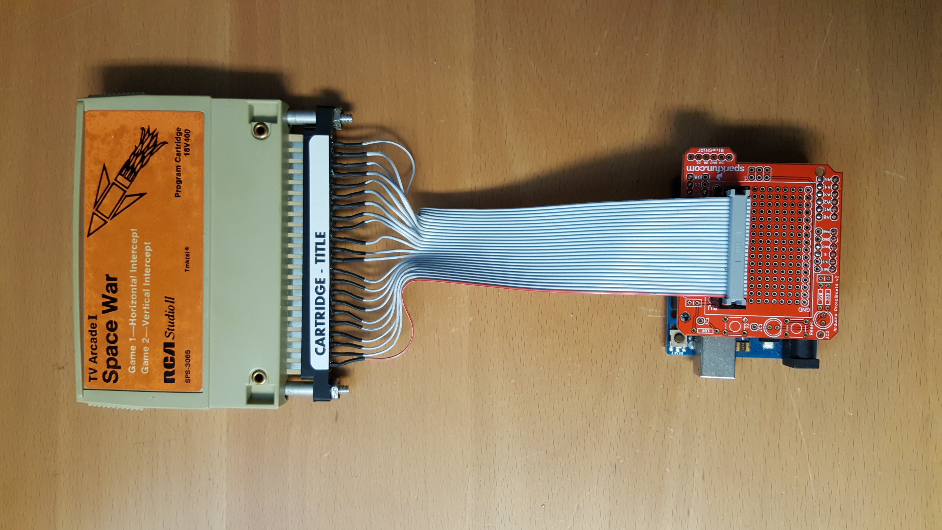
I had already dumped the four ROMs in the Studio II so I could build my own version a while back. Here is a picture of what I built:
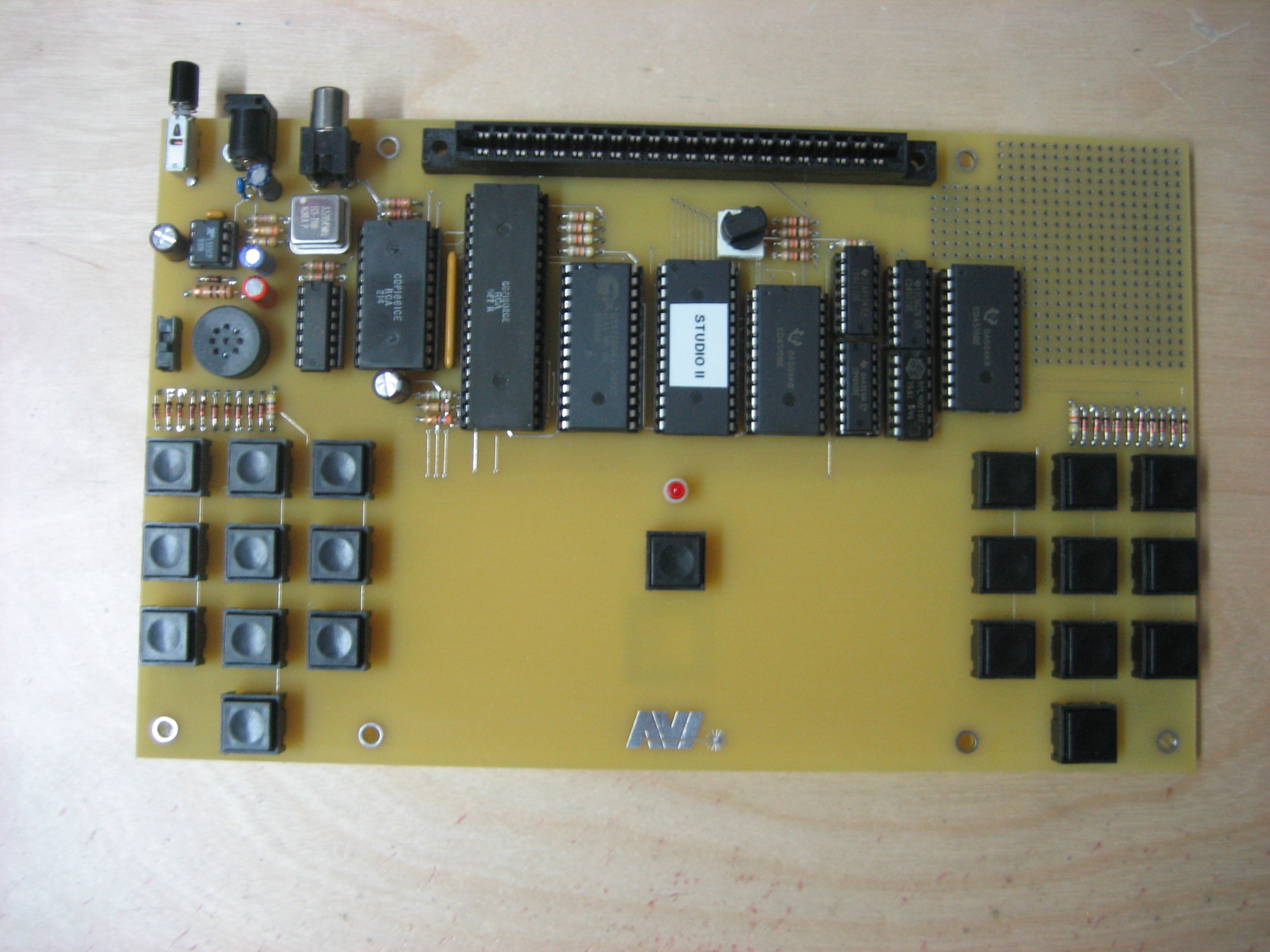
Just to be safe, I used my dumper to do a full 64K memory dump to verify the other four ROMs on the Tester 1 board.
Here is a list of the contents of each of the Tester 1 ROMs.
- 85457 - STUDIO II INTERNAL SYSTEM ROM 1
- 85456 - STUDIO II INTERNAL SYSTEM ROM 2
- 84933 - STUDIO II INTERNAL GAMES ROM 1
- 84932 - STUDIO II INTERNAL GAMES ROM 2
- TESTER 1E ROM1
- TESTER 1F ROM2
I had the firmware of all six ROMs dumped, so I added the dumped code to the schematic document. Here is a link to a zip file with the contents of the six ROMs:
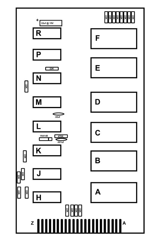
Finally, I added a parts placement diagram to the schematic document.
I would like to thank the buyer of the Tester 1 cartridge for allowing me to preserve this awesome part of 1802 history.
I hope you found this interesting.
ED
Please feel free to contact me at the e-mail address in this image: