
Netronics ELF II Restoration
I am a collector of all things COSMAC so when I saw this Netronics Elf II system appear on eBay, I decided to give it a shot and try to win it. The person listing it had no way to test it, so it was a gamble whether it was complete and working or not.
As luck would have it, I won the auction. What I received was:
- ELF II
- Giant Board
- 2 4K RAM Boards
- Full Basic/Math Board
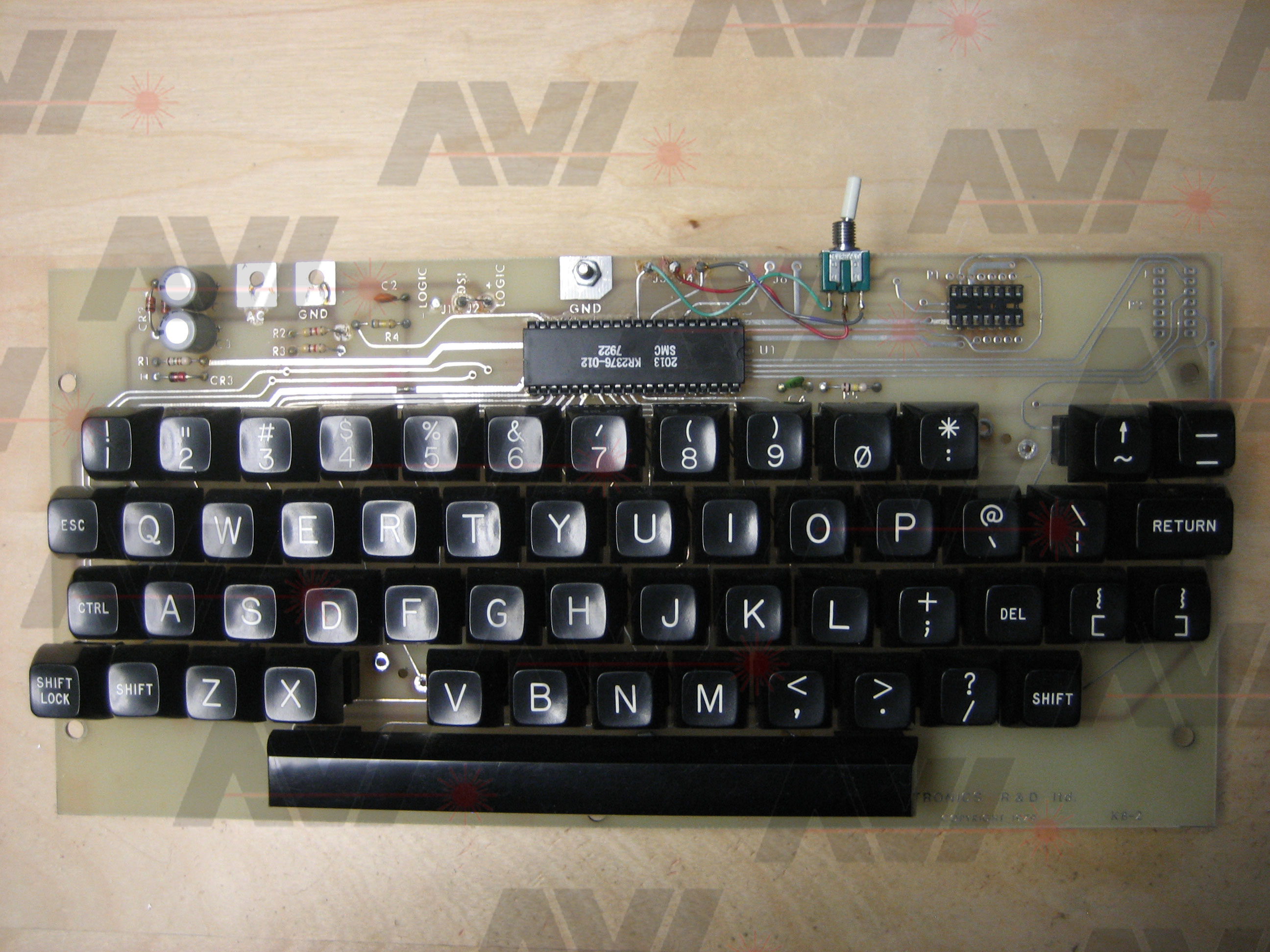
- ASCII keyboard
- Video Display Board
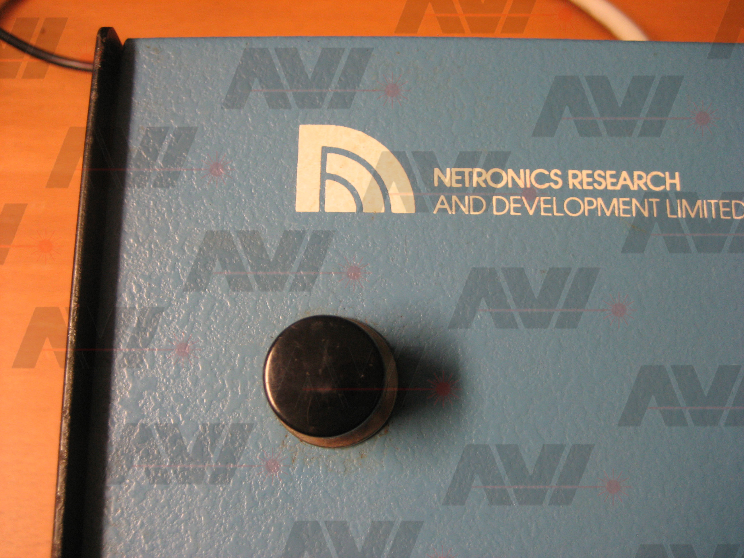
The system was mounted in an original blue Netronics case with original Plexiglass card cover. The keyboard and video display card were also mounted in an original Netronics blue case.
Before I power anything up, I inspected everything. The only physical issue I saw was there was some sort of corrosion on the fingers of the Giant Board. This was easily cleaned with some 91% Isopropyl alcohol.
I decided to get the system working one piece at a time starting with the ELF II board itself.
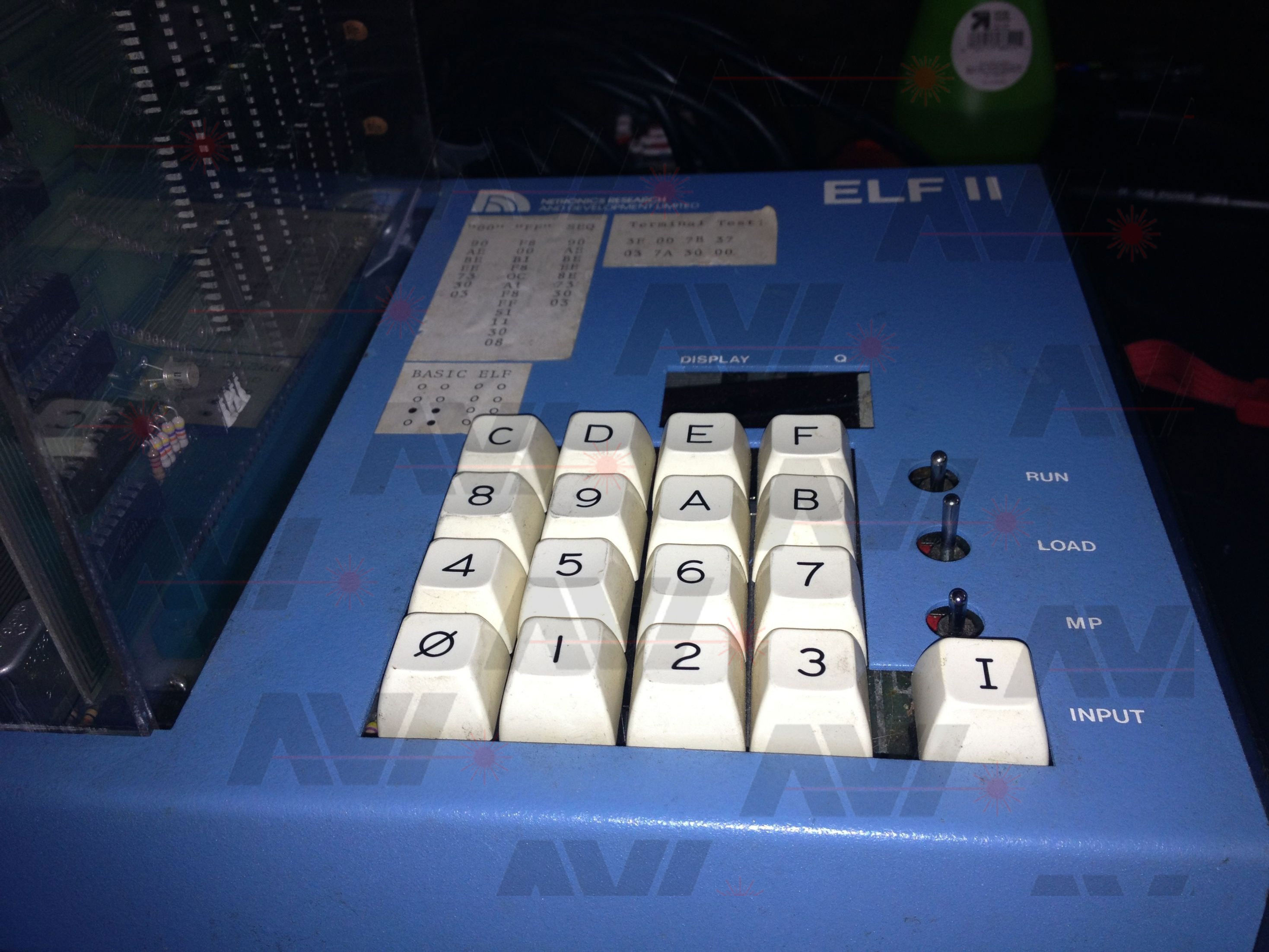
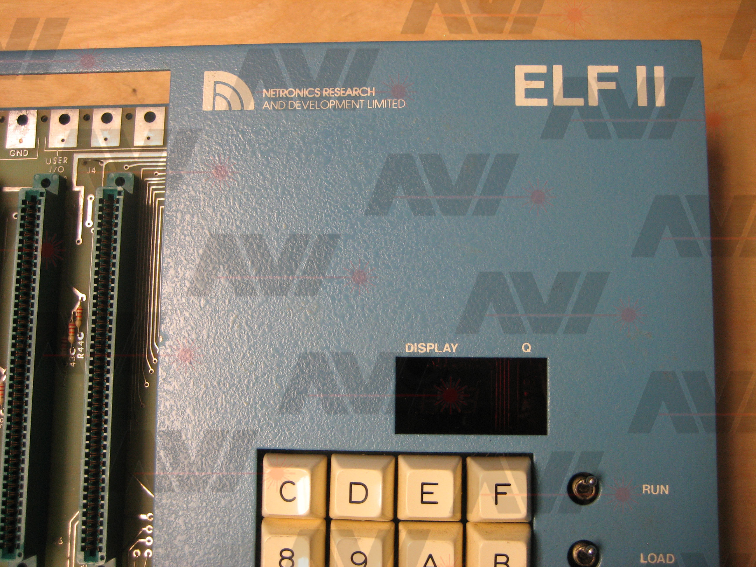
THE ELF II
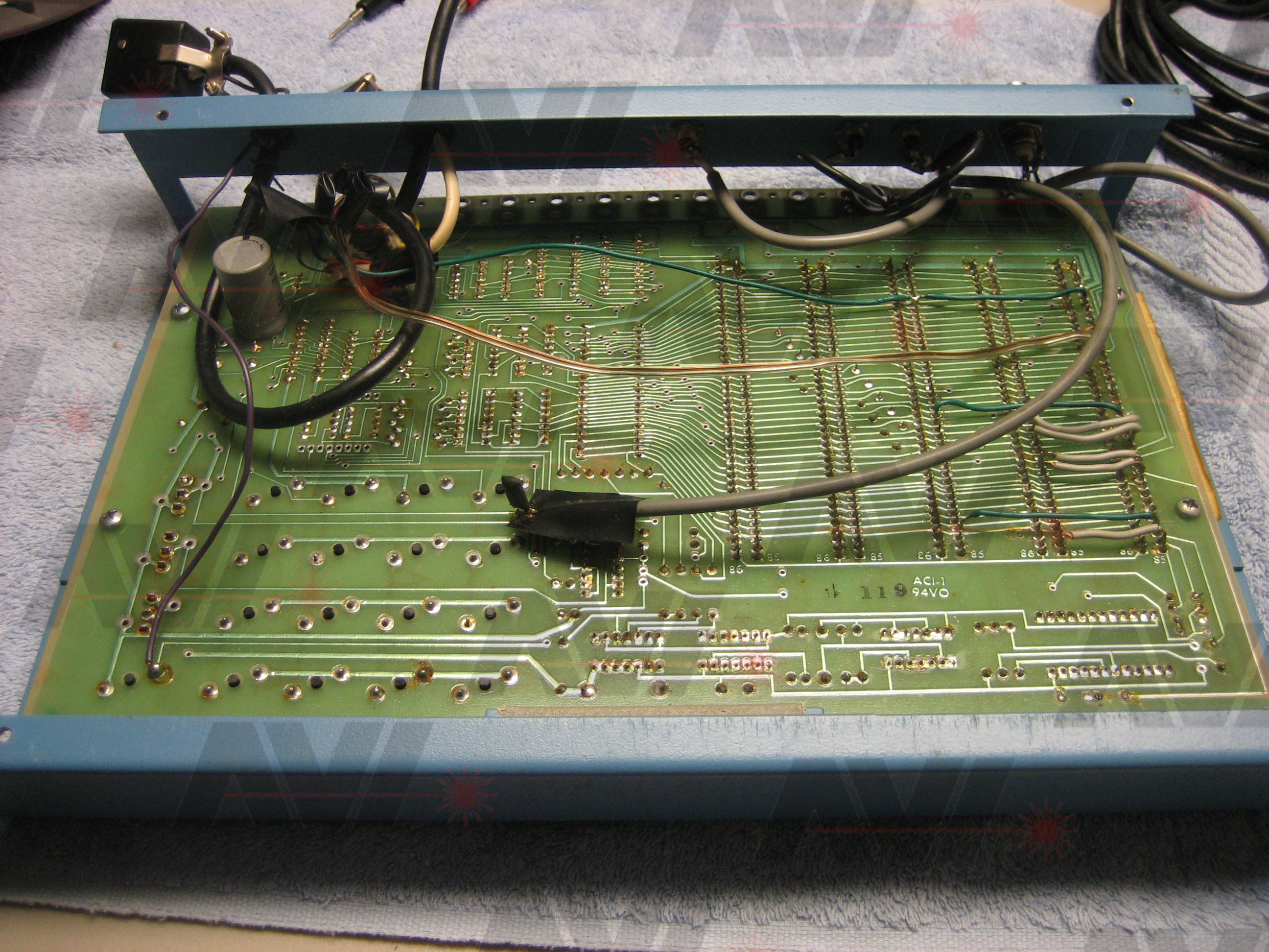
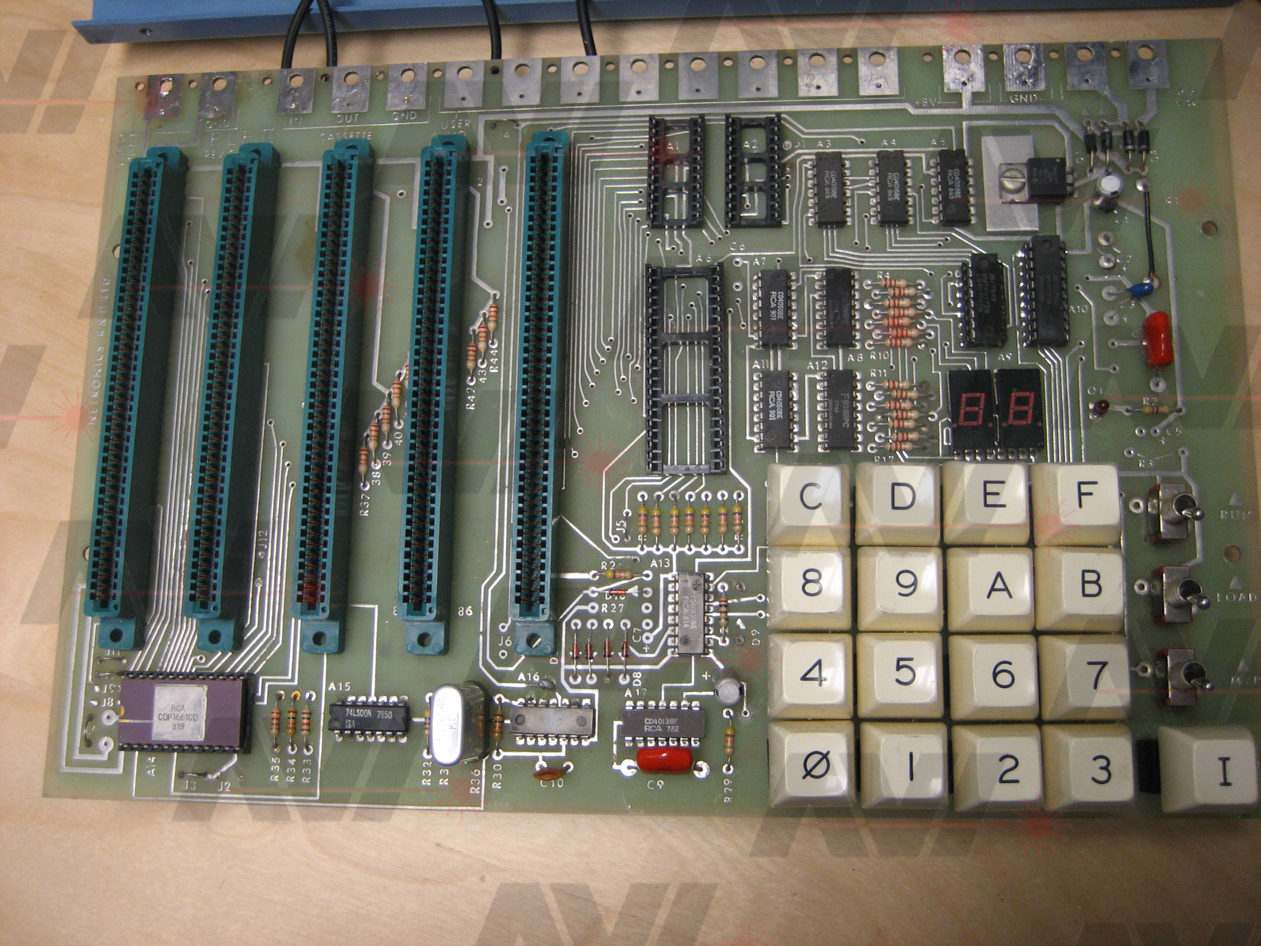
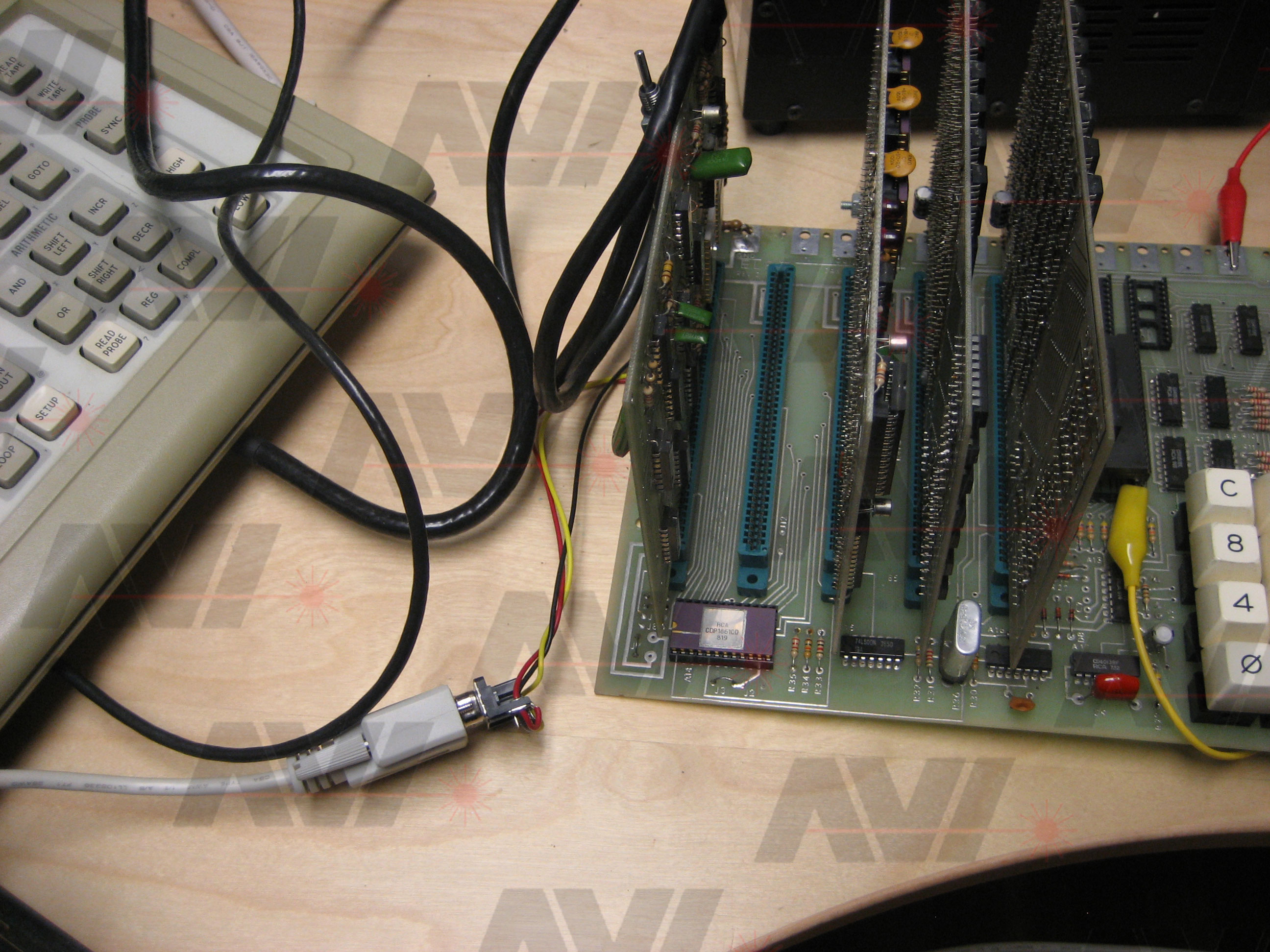
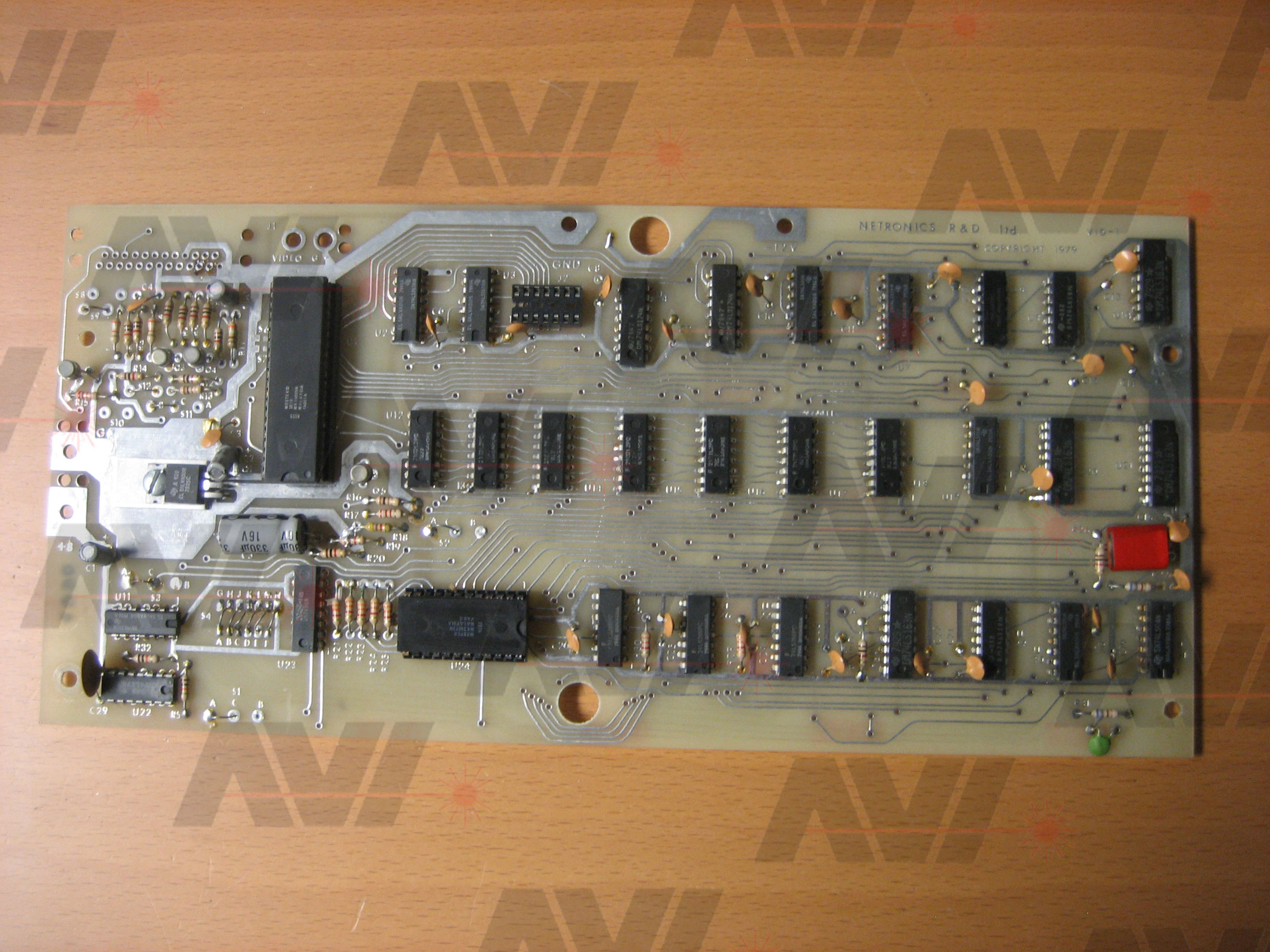
The first thing I did was open the case and inspect the Elf II main board. The first thing I noticed was a bunch of wires between the expansion slots. There was also a mass of wires that were used for interconnection between the keyboard and power supplies. Before taking any action I photographed the wiring from a bunch of different angles just to archive what was there in case I needed it later. Here is an overview of the wiring:
The wiring on slot 5 I understood because the Elf II reserves that slot for the Giant board. I also see three connections to slot 3. The Basic card requires a -8 volt connection for the calculator chip and two n-lines, INP 7 and OUT 7 (67 6F).
The wiring to slot 4 was not something I had seen before. It consisted of mostly n-line connections. I suspect this was for some home made board.
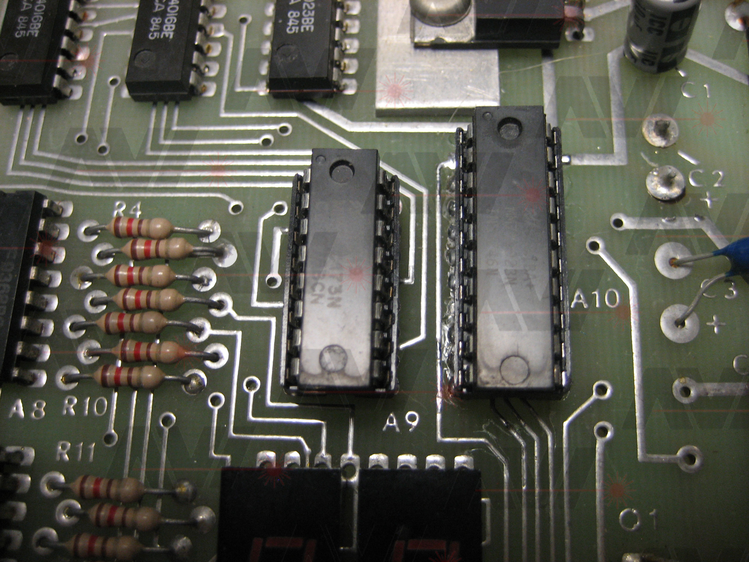
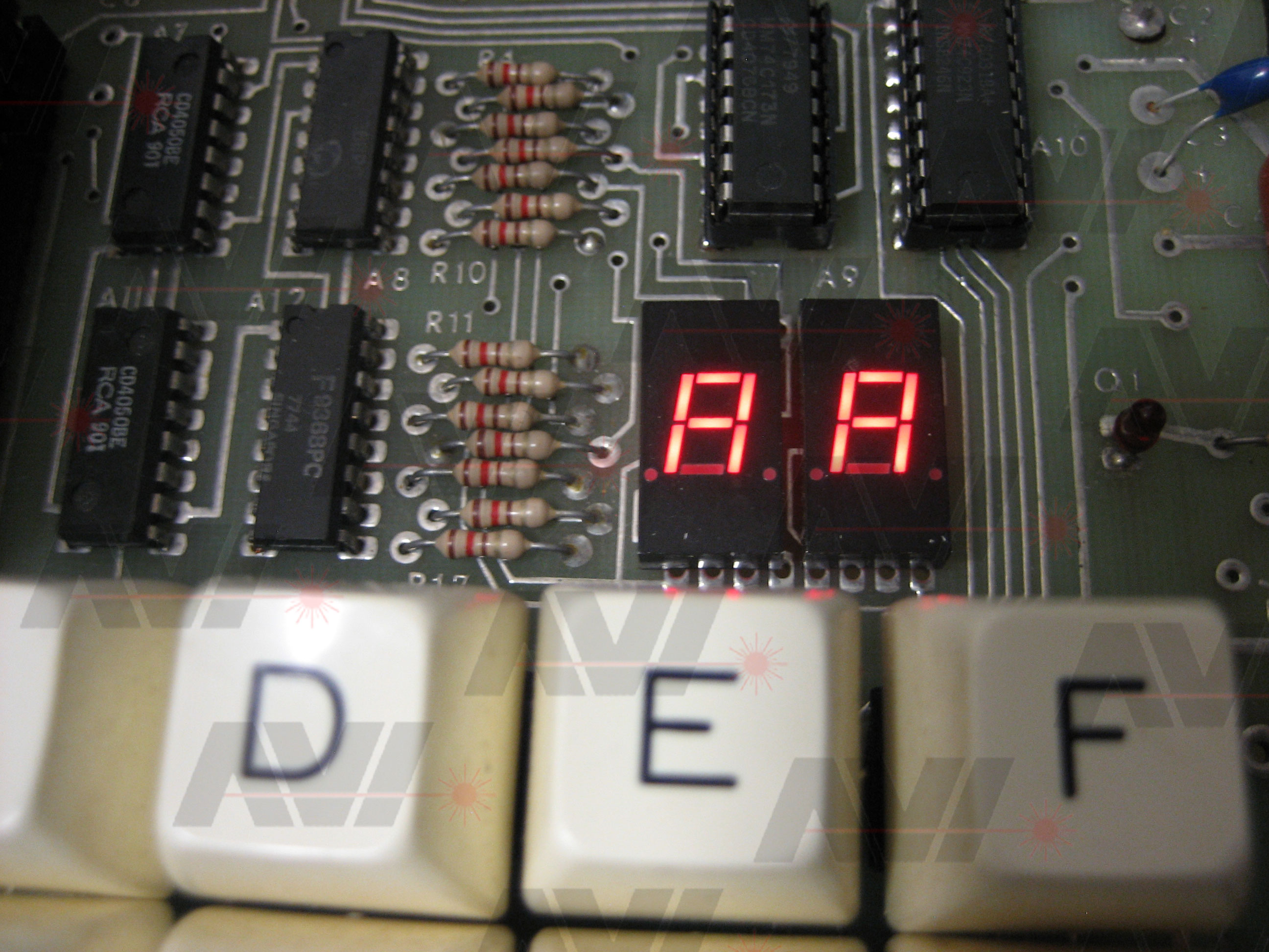
After a visual inspection, I applied +8volts to the system. The LED display lit up and there was no smoke. That was a good start. I flipped the "Load" switch and entered "AA" as a test byte. I pressed the input key, nothing. Using my oscilloscope, I checked to see that the input switch was making contact. It was not. I attached a couple of wire across it and, using a different switch, tried again. Still nothing. I was not seeing any change.
I checked that power was getting to each chip. I had 5 volts everywhere it should be and it had a low ripple. I made sure I had a working oscillator. I could see 3.58 MHz as expected. I checked for a divided by 2 clock. I saw a 1.78 MHz signal as expected. I used the oscilloscope to view the address and data bus. The address bus looked fine, but the data bus was being suppressed. Instead of a full 5 volt swing, I was seeing a few lines that were only reaching about 2.1 volts. It appeared the data bus was hanging.
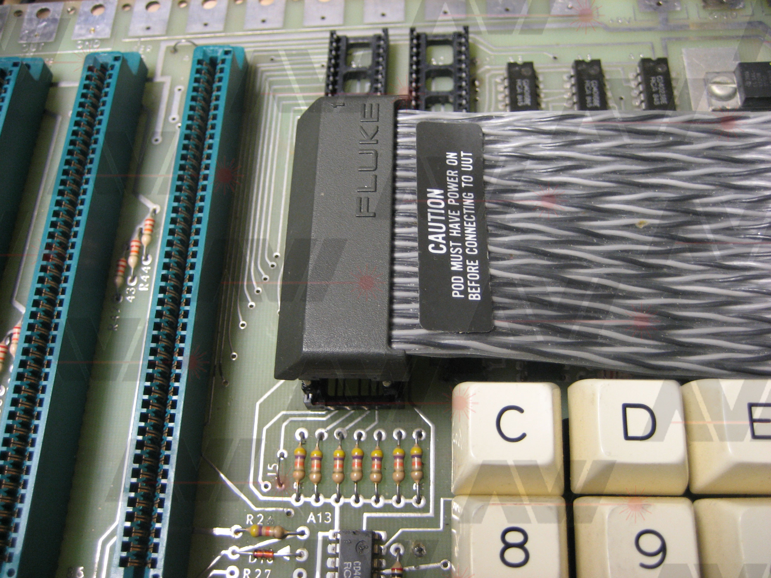
At this point I removed all the wires from the back of the PCB. I then removed the 1802 and 1861 chips. I attempted to install the cable form my Fluke 9010A troubleshooter, but the socket that was installed on the PCB had tall plastic on it's outer edge preventing the fluke from making contact.
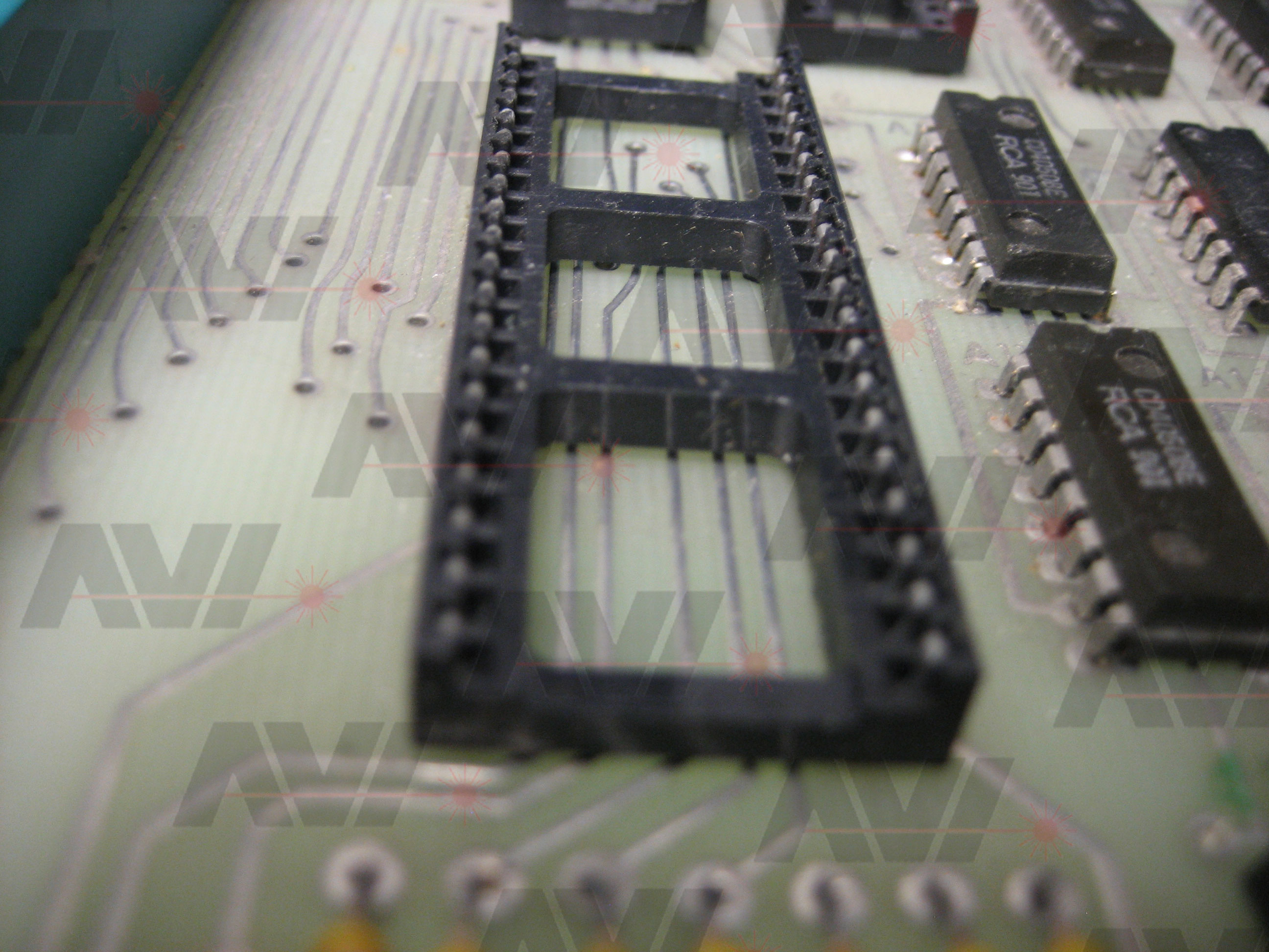
So I built a little adapter.
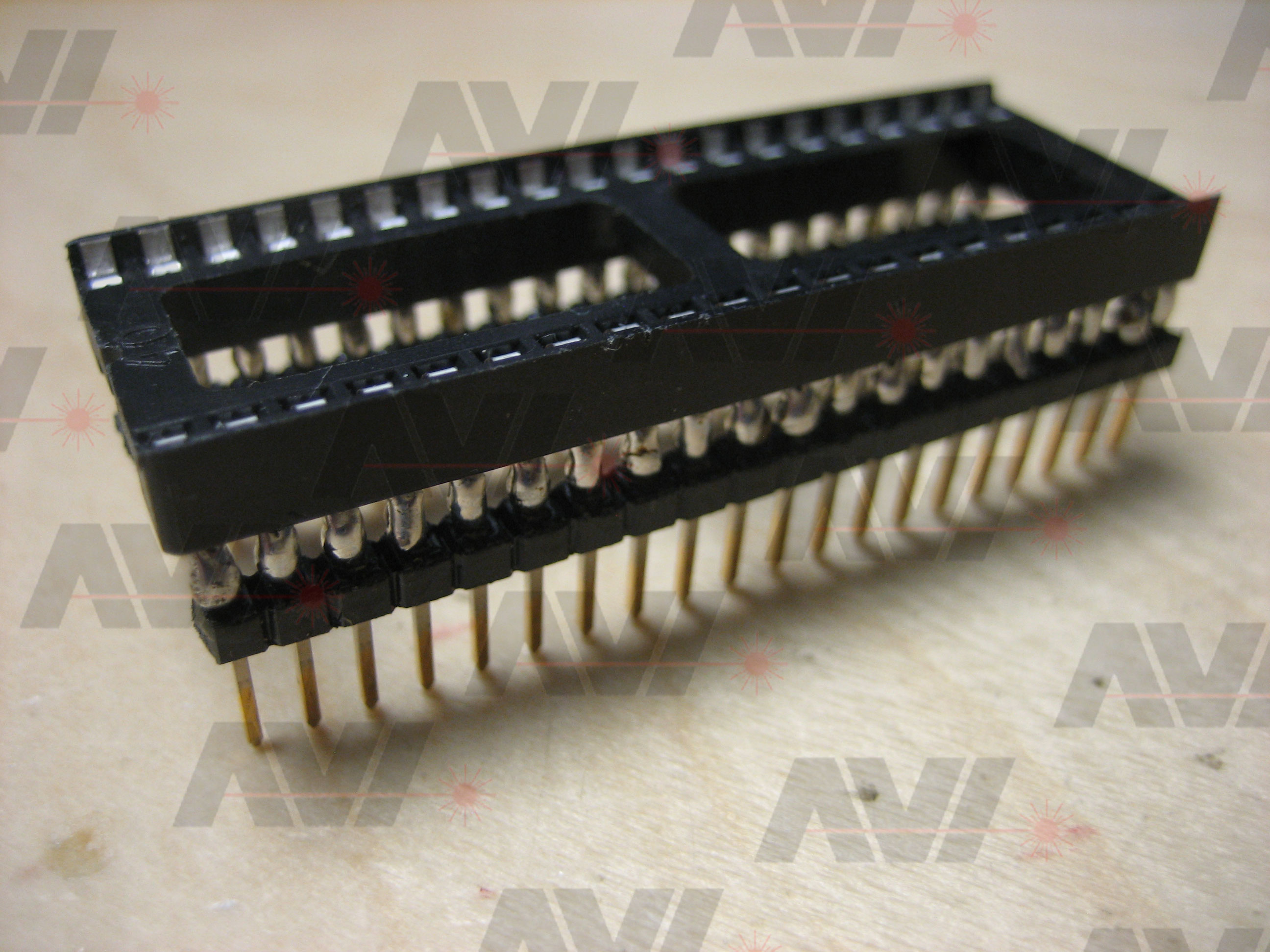
With the adapter I was able to get he fluke connected.
I ran a "Bus Test" and saw that the data bus was in fact having a problem. It was showing that bits 5 and 6 were shorted together a some point.
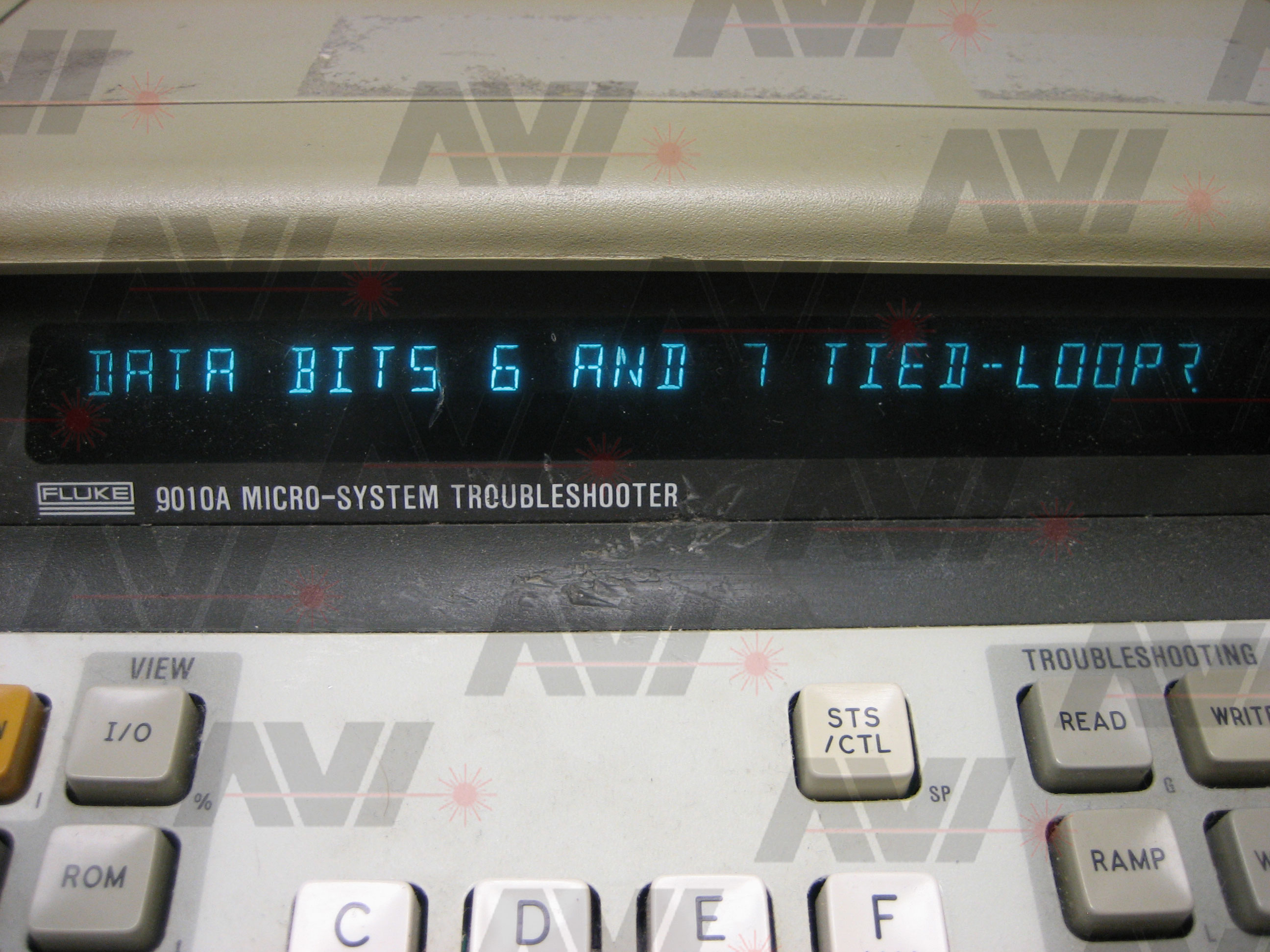
The fluke displays address and data bits as 1-8 instead of what I am used to which is 0-7.
I did another visual inspection, focusing on the data bus traces, but saw nothing wrong.
At this point the only devices connected to the data bus were:
- Keyboard encoder and latch
- buffers going to the 9368 display chips
- 4016 bi-lateral switch chips
The two 2101 RAM chips would have also been on the bus, but when I received this system they were not installed.
With my scope I checked for a DA (data available) signal from the keyboard encoder chip as I pressed keys on the keyboard, but did not see any. I then checked the scan lines going to the key matrix. I had a signal on only two of the lines. The 74C923 chip appeared to be bad so I removed it from the circuit. Before replacing the chip, I re-tested the data bus and saw that two of the lines were looking normal. There was still one not right.
I removed the chip from the PCB and installed a socket. I replaced the chip and checked the outputs from it again. I was now getting a DA signal on each key press and could see valid data on the 4 bit outputs. I could see that the DA and four data lines were getting to the 74C173 latch that holds the low nibble of the input data, but the outputs were not responding at all. I removed it, installed a socket and replaced the chip. After checking again, had valid data that followed what I was entering.
Once again, I entered "AA" and pressed the external input switch I had attached. Still nothing.
For my own sanity I decided to reverse out all the modifications on the Elf II required by the Giant board and installed a couple of 2101 RAM chips. I tried loading a byte from the keyboard again. This time it worked!
I entered a short program that counts from 00h to FFh. I ran it and saw that the displays were able to display all digits correctly with balanced brightness.
I entered 7B 00 and saw the "Q" LED light when I ran it.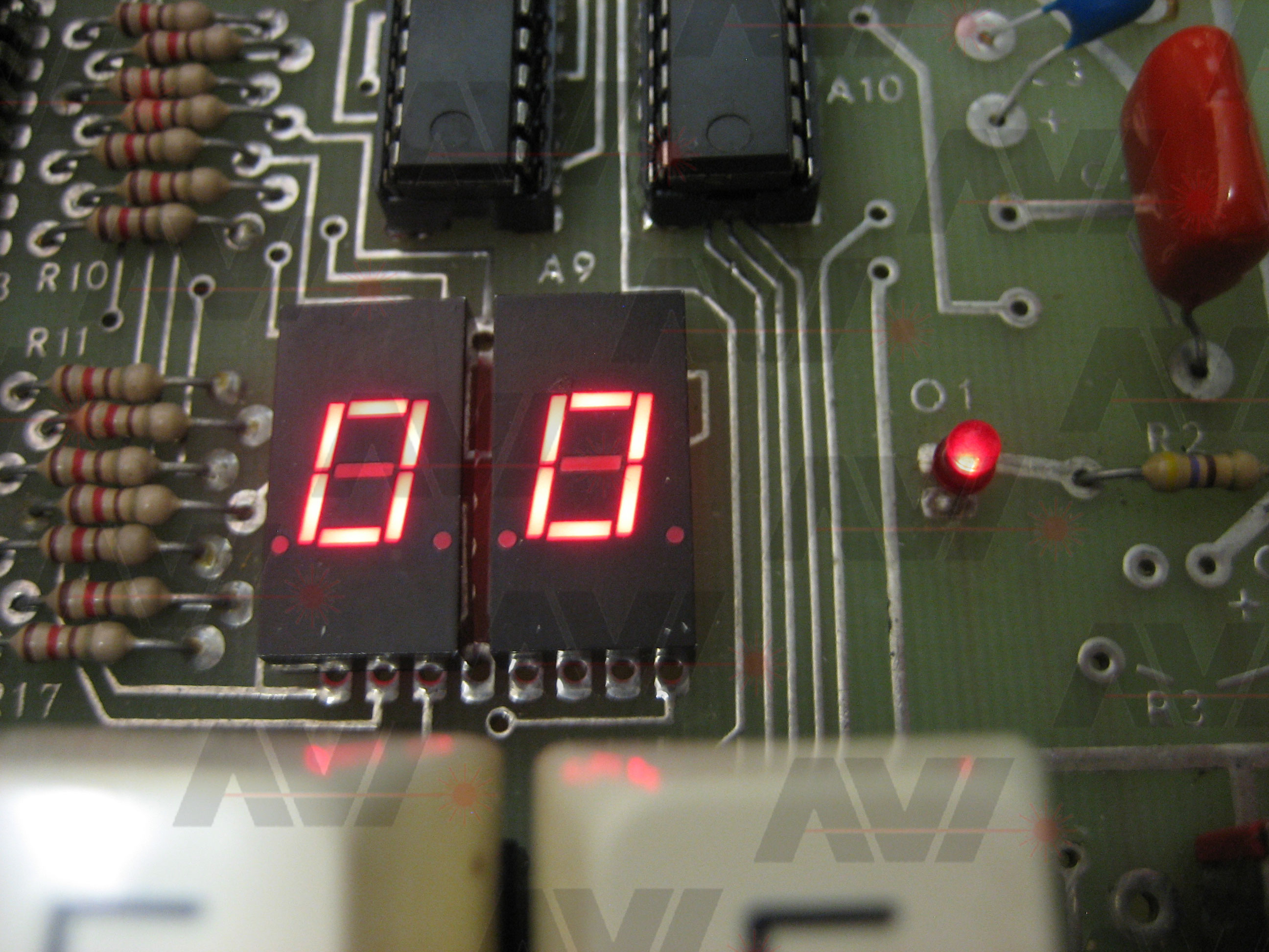
At this point I removed the fluke cable and reinstalled the 1802 and 1861 chips. I did a few more tests with the real 1802 chip installed. Everything still worked.
I used the example from Popular Electronics, July 1977 to test the video for real.
90 B1 B2 B3 B4 F8 2D A3 F8 3F A2 F8 11 A1 D3 72 70 22 78 22 52 C4 C4 C4 F8 00 B0 F8 00 A0 80 E2 E2 20 A0 E2 20 A0 E2 20 A0 3C 1E 30 0F E2 69 3F 2F 6C A4 37 33 3F 35 6C 54 14 30 33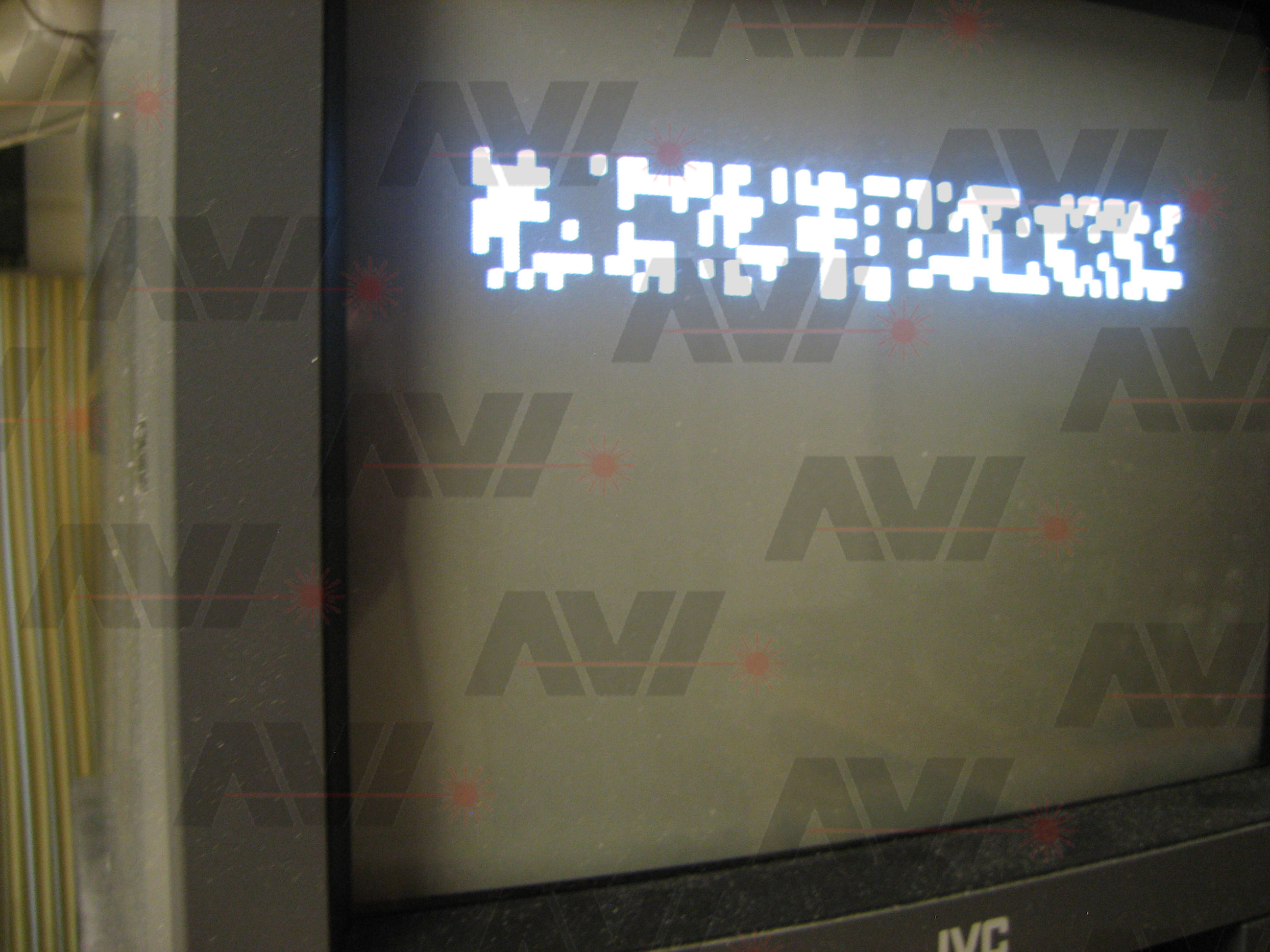
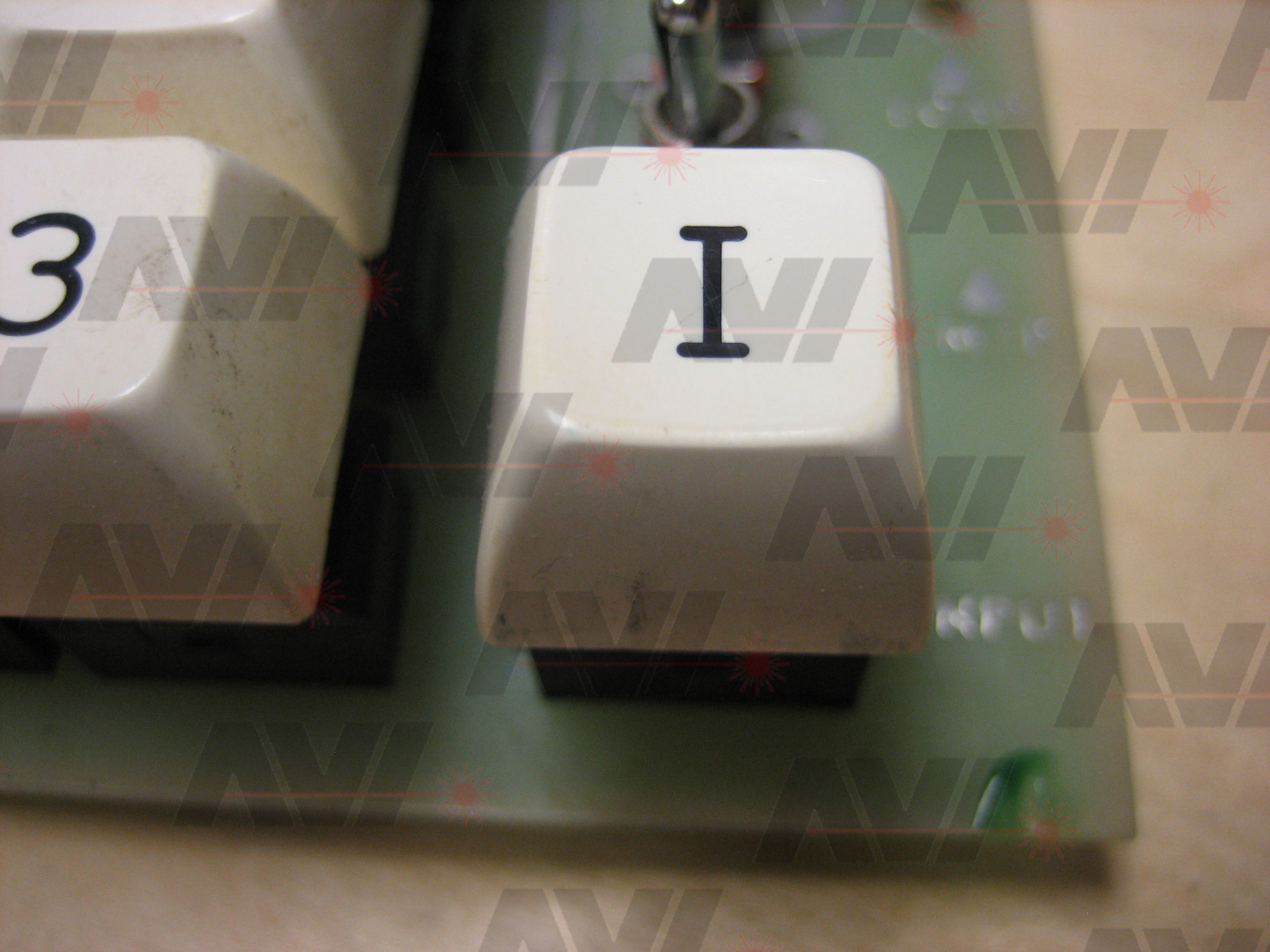
The only thing left to fix was the input switch. I removed the switch from the PCB and tested it with my meter. There was not connectivity when pressed. I decided to open it to see what was wrong. The buttons enclosure was made of plastic and appeared to be either heat of ultrasonically welded shut. Using a razor knife, I carefully cut the enclosure open.
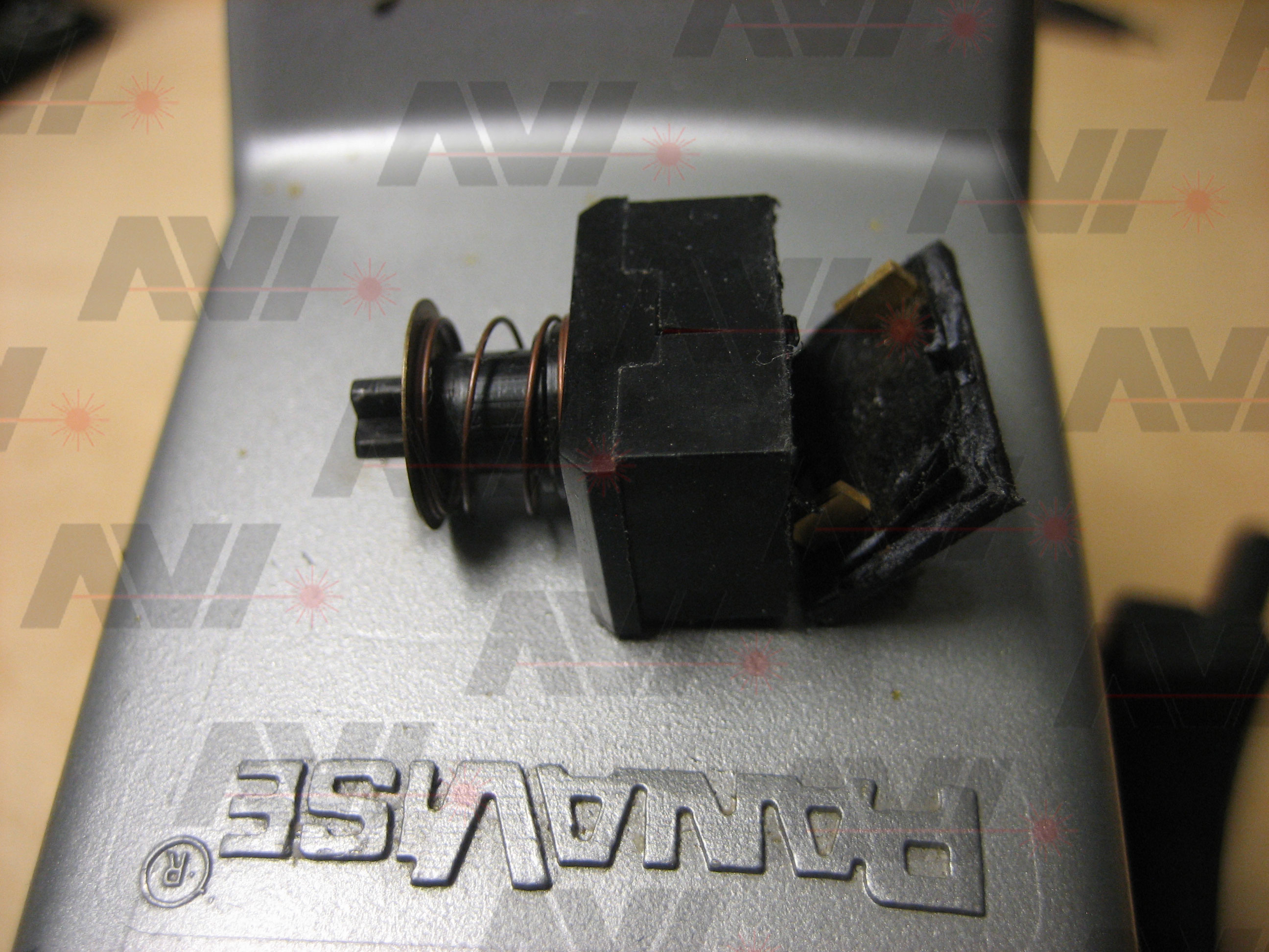
Inside I could see quite a bit of wear on the contacts. As I pressed the button I could also see that one side of the contact spring was not making contact with the top of the terminals. It looked like someone had been pounding on this switch.
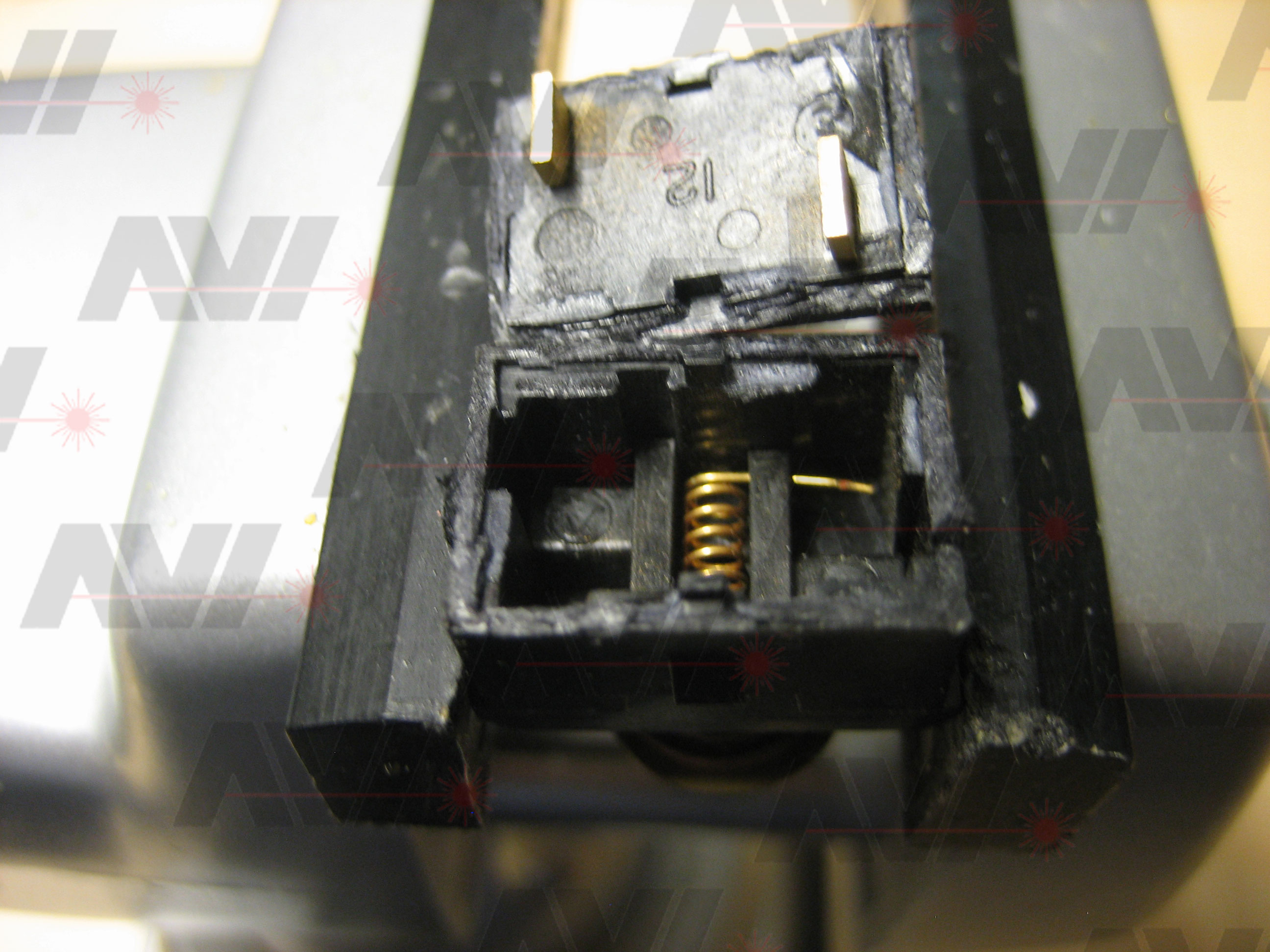
I decide to try and bend one of the ends of the spring to make better contact. After doing this the switch worked a little better, but not good enough.
I collect 1802 and COSMAC related items, you can see some of them in my gallery located here:
/GALLERY/GALLERY.phpIn my collection, I also have a bunch of boards and systems in bad shape. I have a couple different "Netronics Programmers".
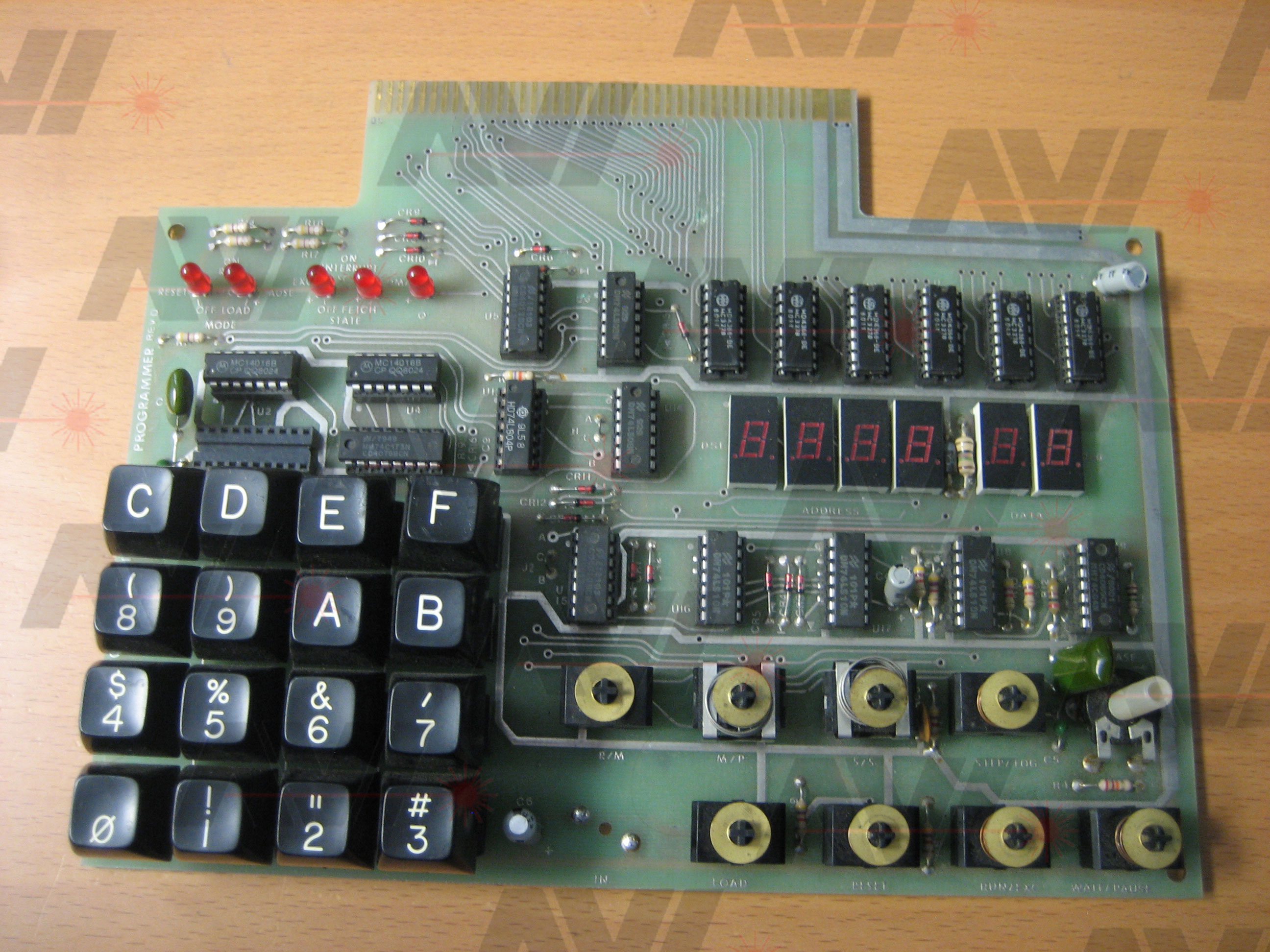
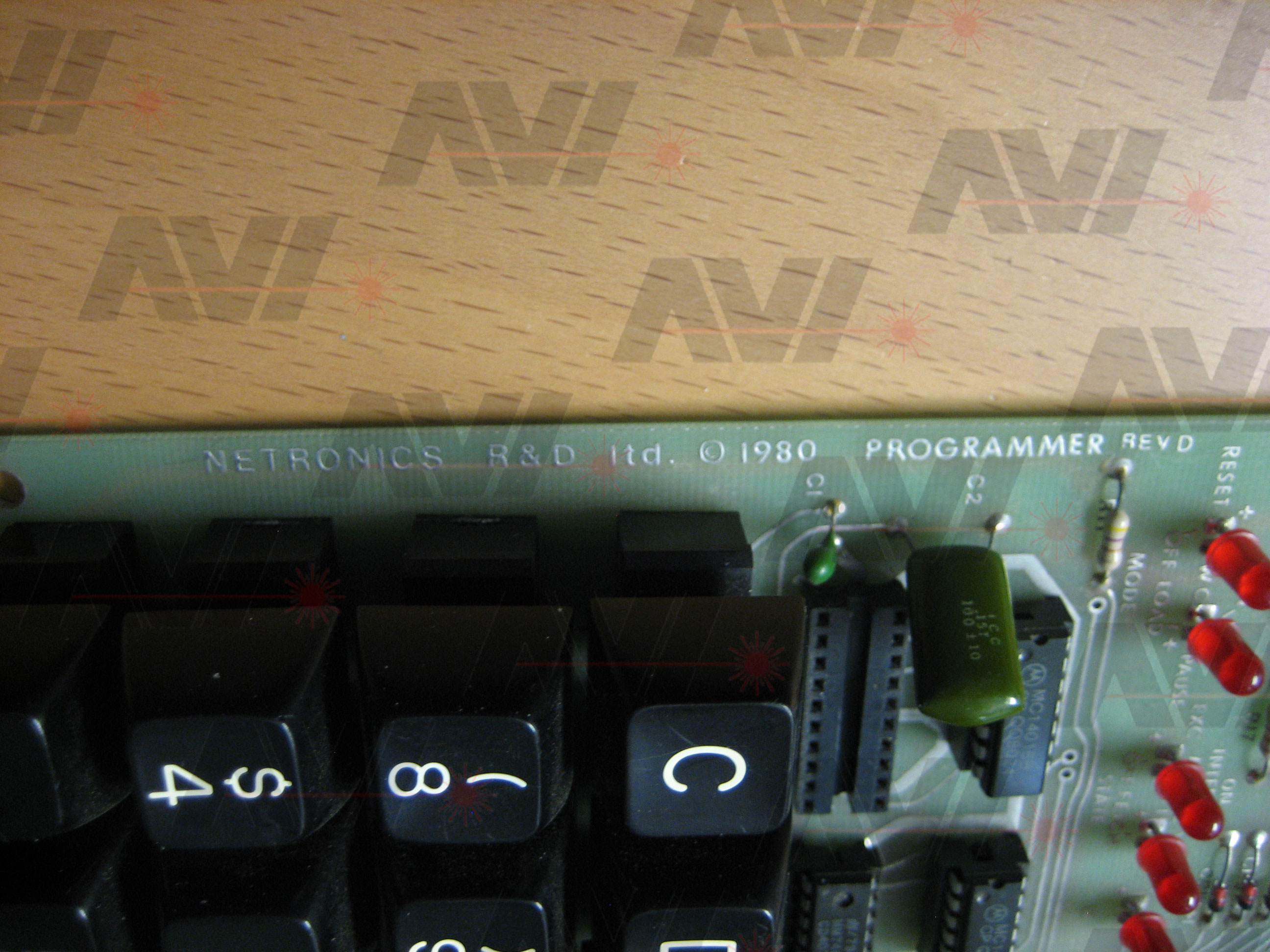
This system was written up in Popular Electronics, November 1980. One of the boards I have is missing components and keycaps. It does however have the exact switches that are used on the Elf II.
I removed the temporary switch I had added, then removed one of the Stackpole switches from the "Netronics Programmer". I installed the switch and replaced the "I" keycap. The basic Elf II was now working.
The last thing I did before moving on was to clean the square interconnection pads at the back edge of the PCB.
ELF 2 AND GIANT BOARD
I started testing the Giant board by doing the required modifications to the ELF II board. I entered "C0 F0 00", the command to get to monitor, it did not work.
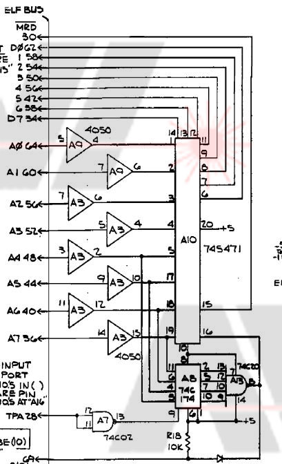
Using my scope, I looked to make sure all data bus lines were getting to the 74C471 PROM, a few bits were not there. This was caused by the corrosion I describe above. I had not cleaned the fingers on the board good enough.
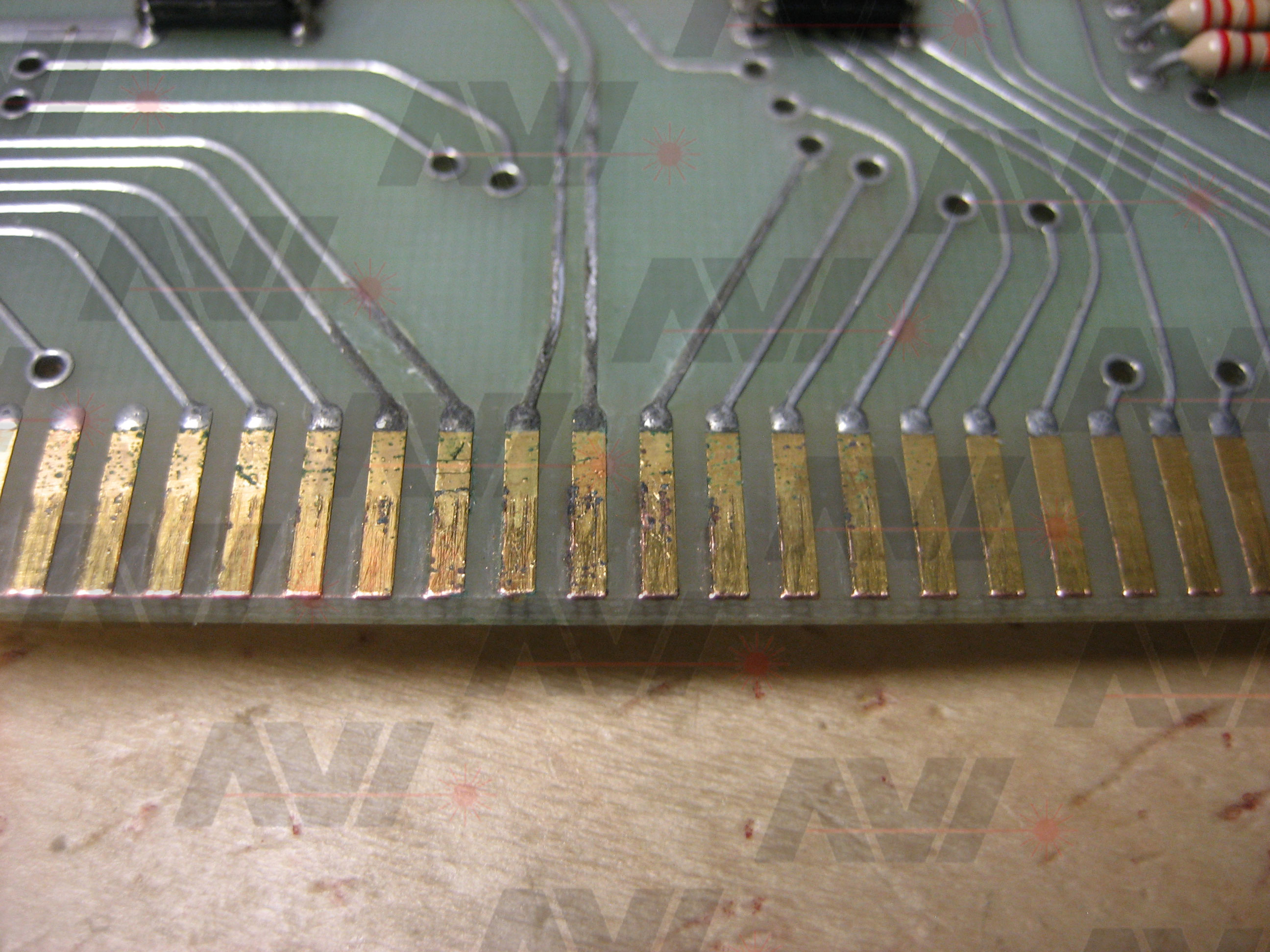
After thoroughly cleaning and burnishing the fingers (the old pencil eraser trick), the entire data bus was making it to the PROM.
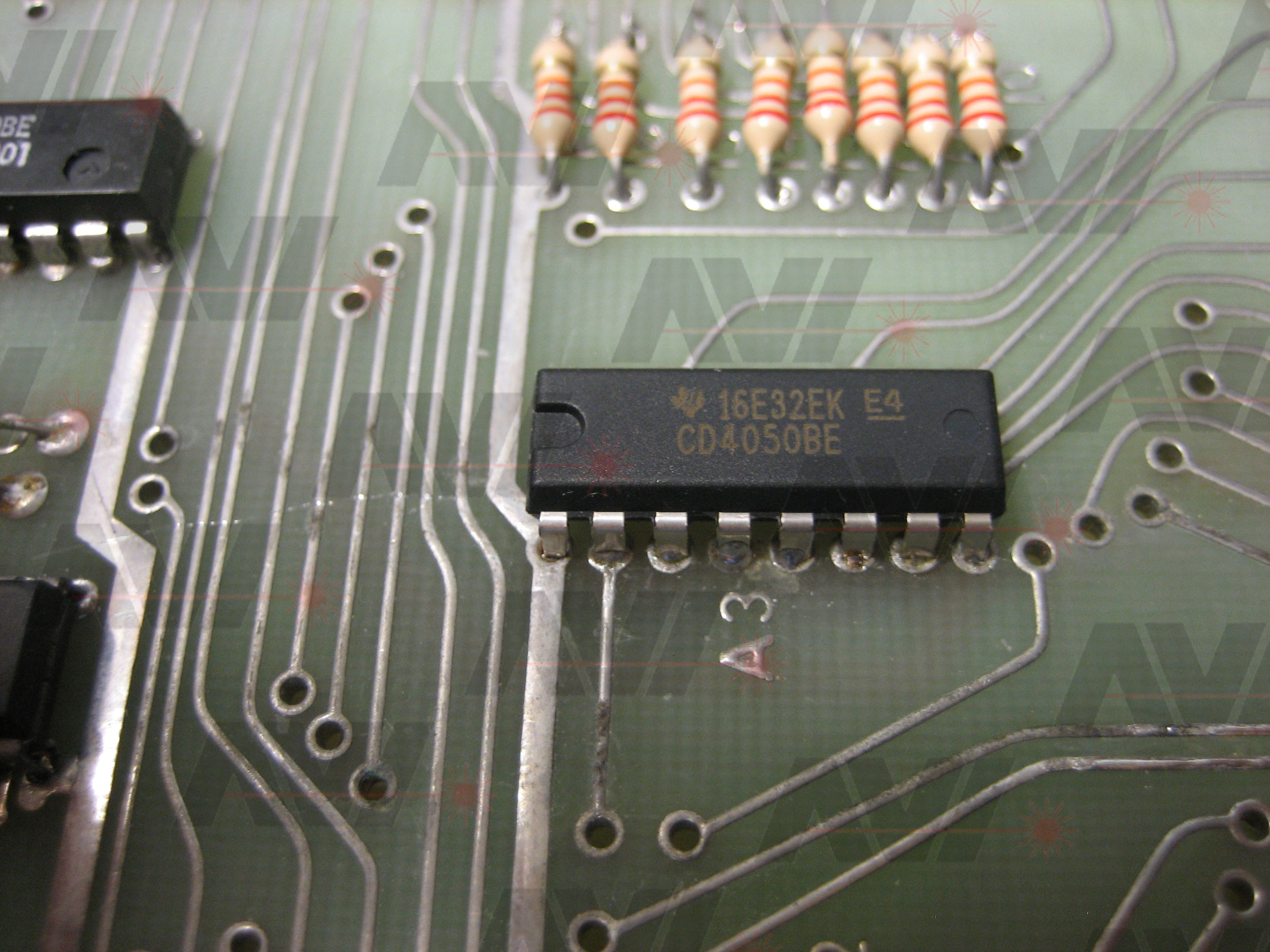
I then checked for good address signals at the PROM. All were fine except bit 6. I traced the line from the 1802 right up to a 4050 buffer. The signal was good on the input, but bit 6 was not getting through. I checked for shorts on the output side, but found none. I replaced the 4050 and now bit 6 is working too.
The /MRD signal was good too. The only signal missing was the chip select from the PROM.
The chip select circuit is comprised of:
- 74C02
- 74C85
- 74C174
The first thing I looked for was an inverted TPA pulse at the 74c174 chip. I followed this back and could see the TPA signal on the input of the 74C02 that was being used as an inverter. I did not have this chip on hand, so I placed an order for it (and a bunch of other chips) from Unicorn electronics (http://unicornelectronics.com/index.htm).
When the parts arrived, I removed and replaced the 74C02. I now had a good, inverted, TPA signal reaching the latch. But the monitor still did not work. I checked the inputs to the latch using my scope and saw that I was getting good, buffered, address signals. I checked the outputs and saw that I was only getting a signal on two of the four lines. I replaced the 74C174. I now see a good chip select signal when jumping to the PROM. The monitor was now working.
I decided to start working on the RAM cards and would come back to the Giant board after I had them working.
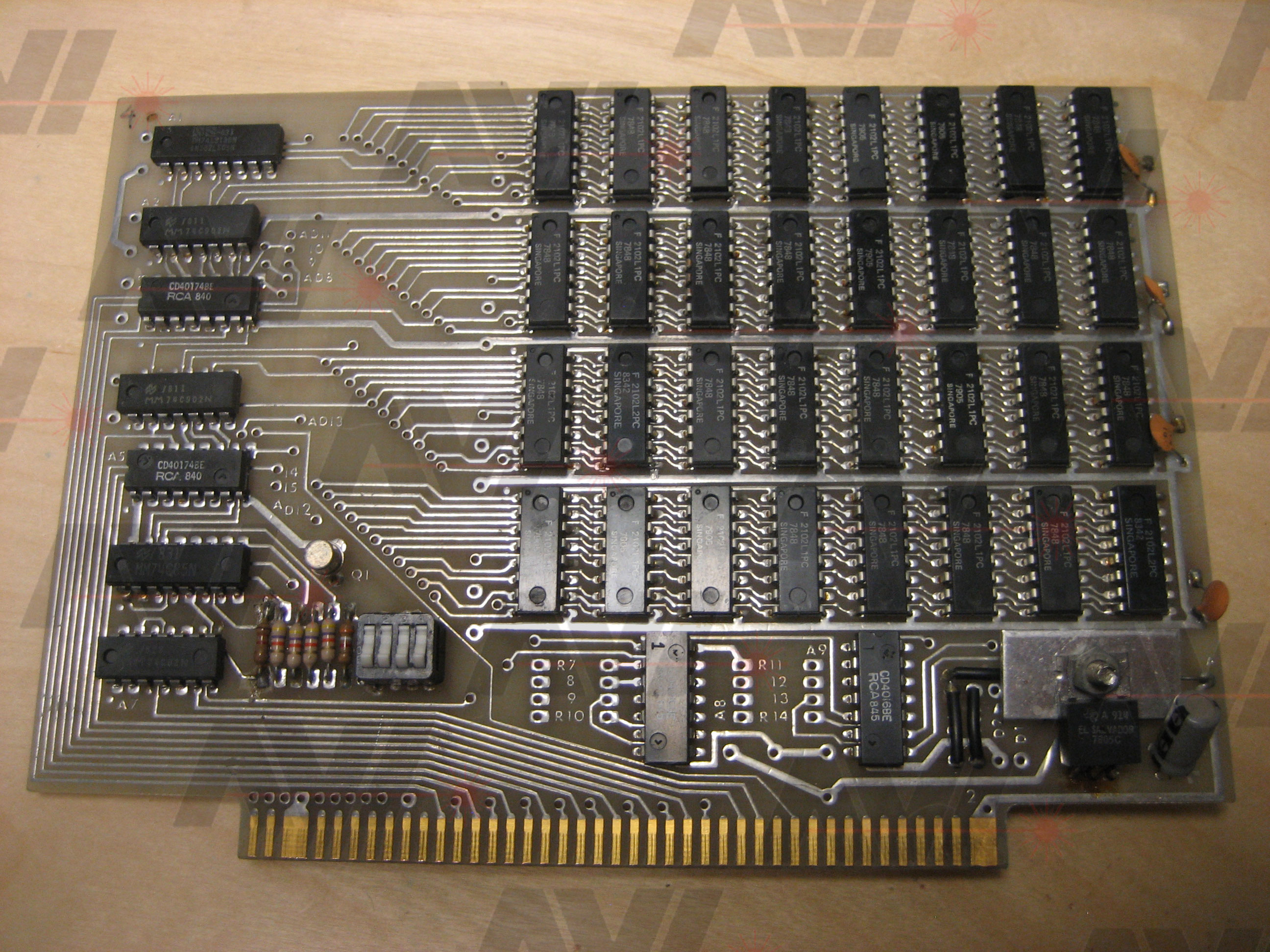
ELF 2 AND 4K RAM CARD 1
I set the address "jumpers" on the first RAM card to 0000h-0FFFh using a table on the ram card schematic as a reference. In the assembly instructions for the 4K RAM cards the builder is offered the option of replacing the "jumpers" with a four position dip switch, which both of the boards I received have installed.
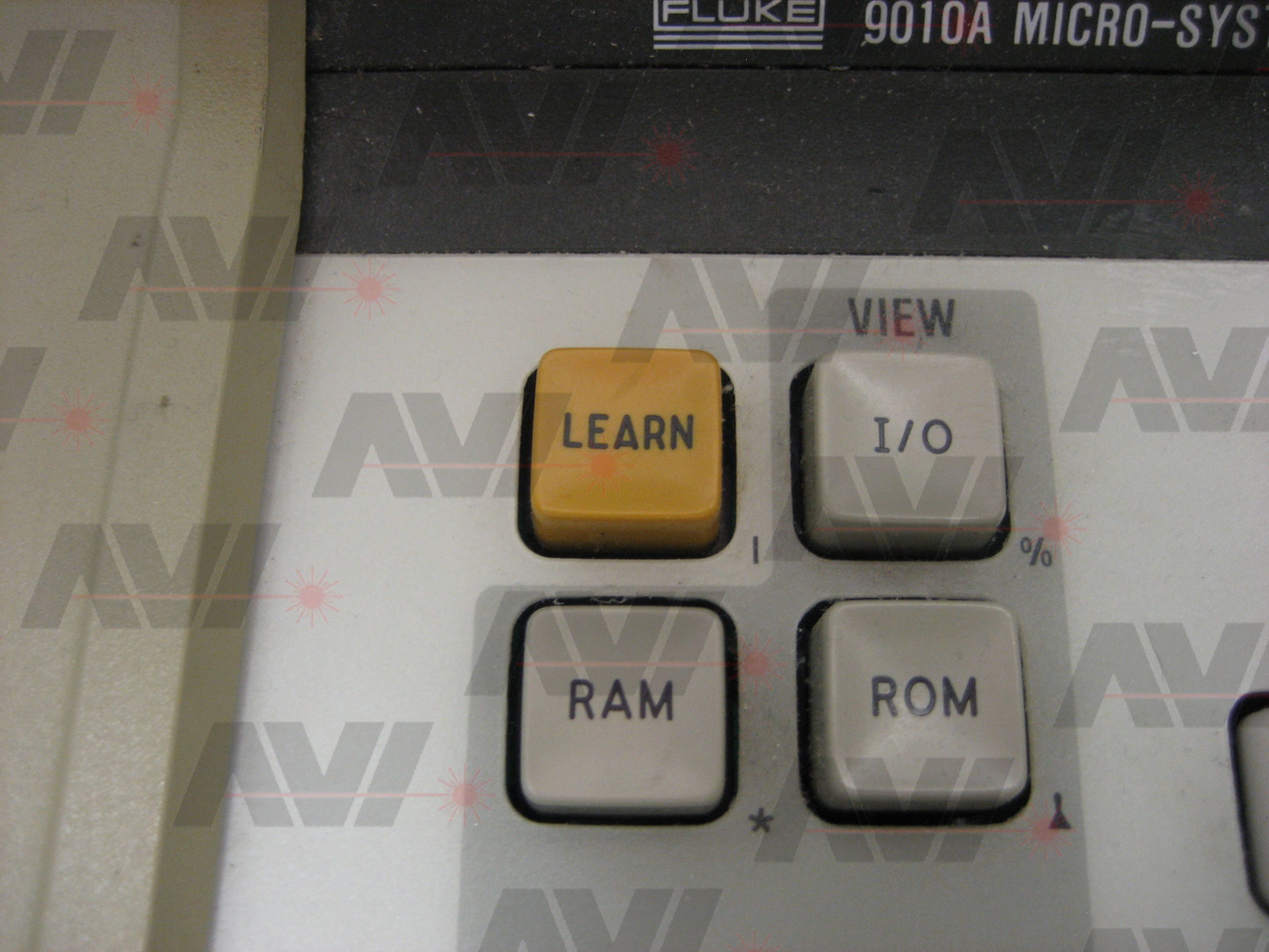
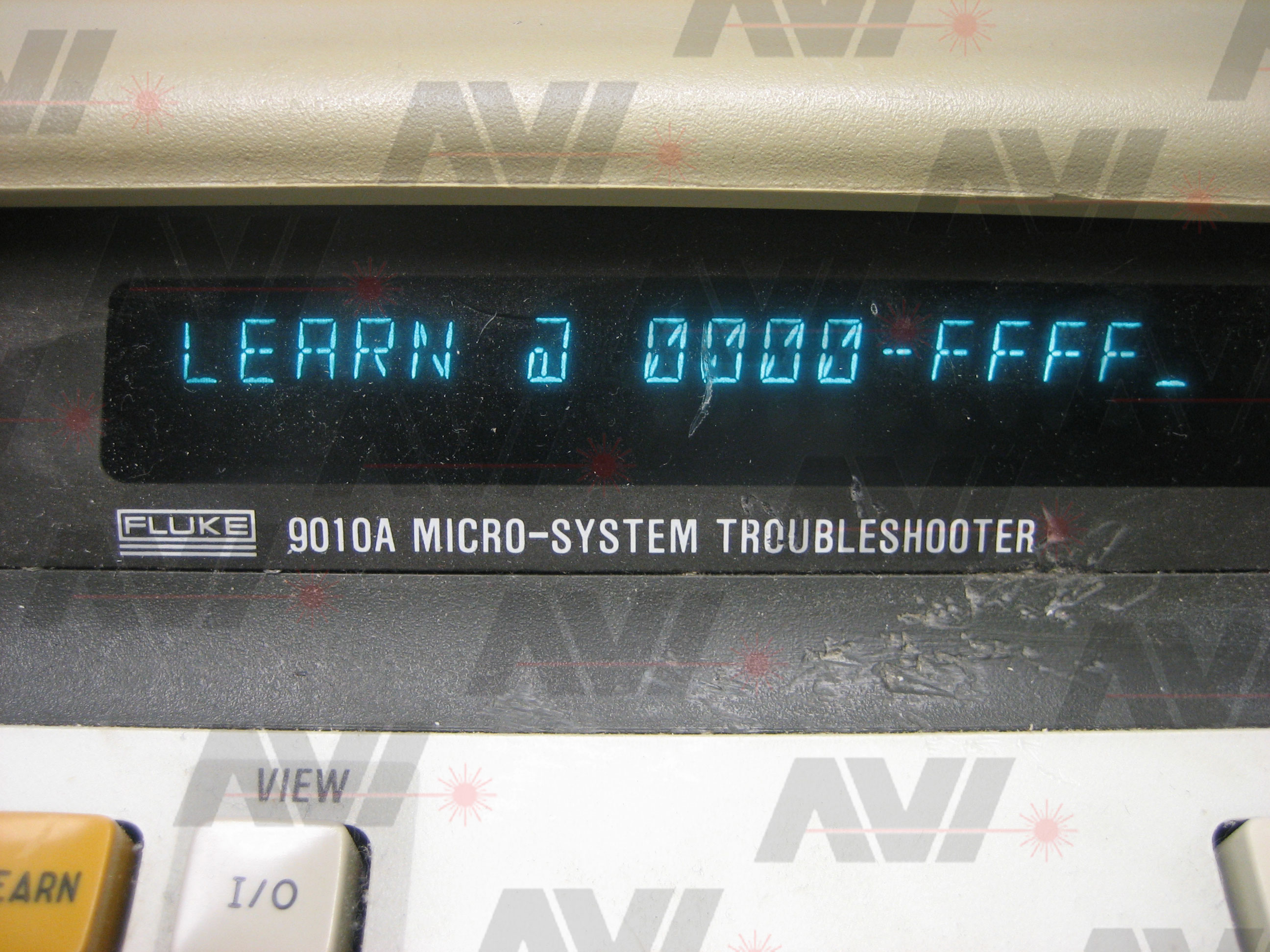
The system would not start. I removed the two 2101 RAMs installed on the Elf II PCB. It still did not work. On the Elf II, I removed the 1802 again and re-installed the fluke. Using the fluke I did a "LEARN".
This makes the fluke try to read and write to every address in the range entered. It allows me to generate a memory map of a system.
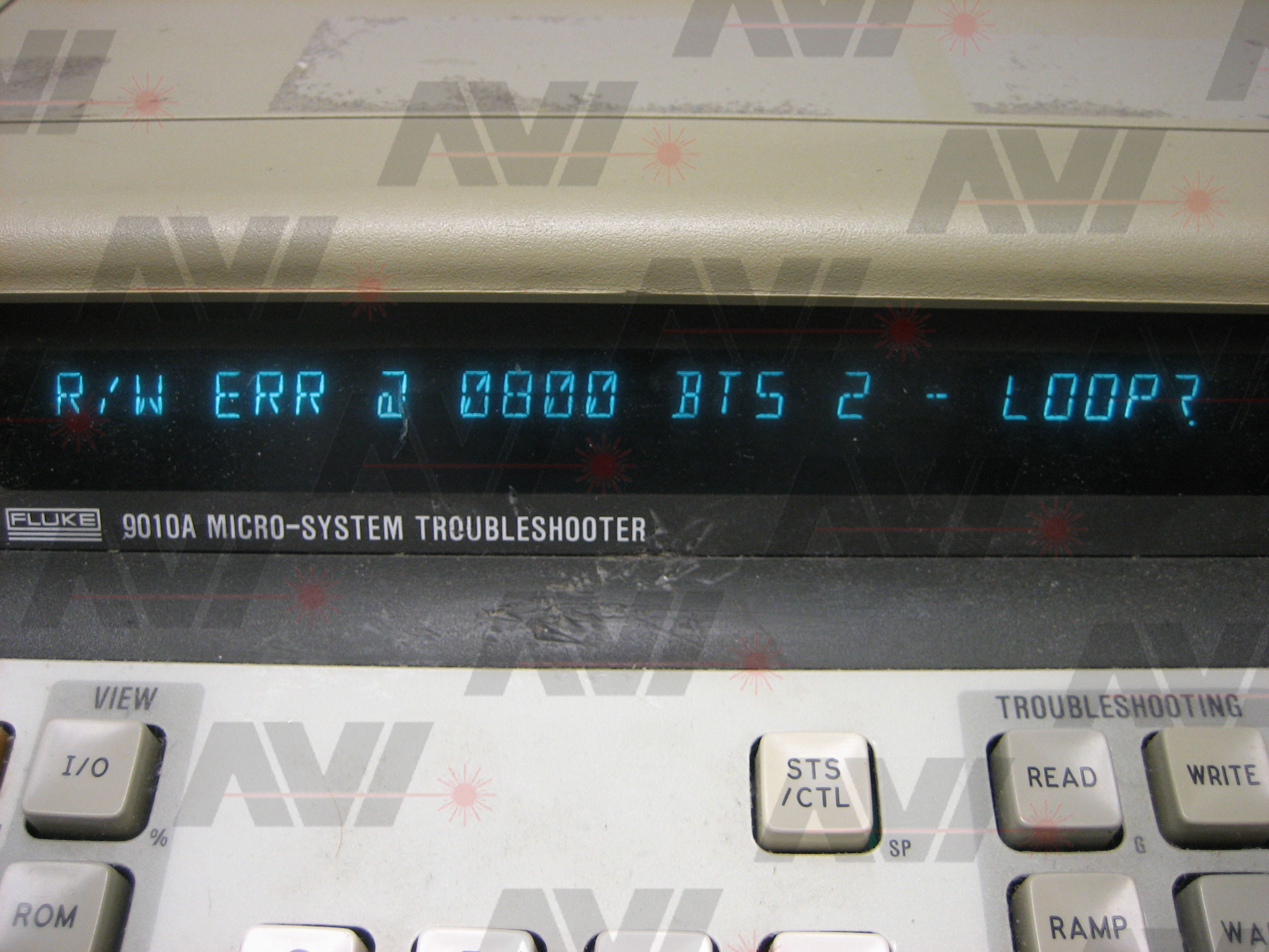
The fluke found RAM where I expected it, in the 0000h to 0FFFh, but it indicated that there was something wrong on one of the data lines. I did a "RAM SHORT" test and found errors in two different banks. The errors were isolated to the 0800h-0BFFh and 0C00h - 0FFFh ranges. Bit 2 in the 0800h range and bit 8 in the 0C00h range.
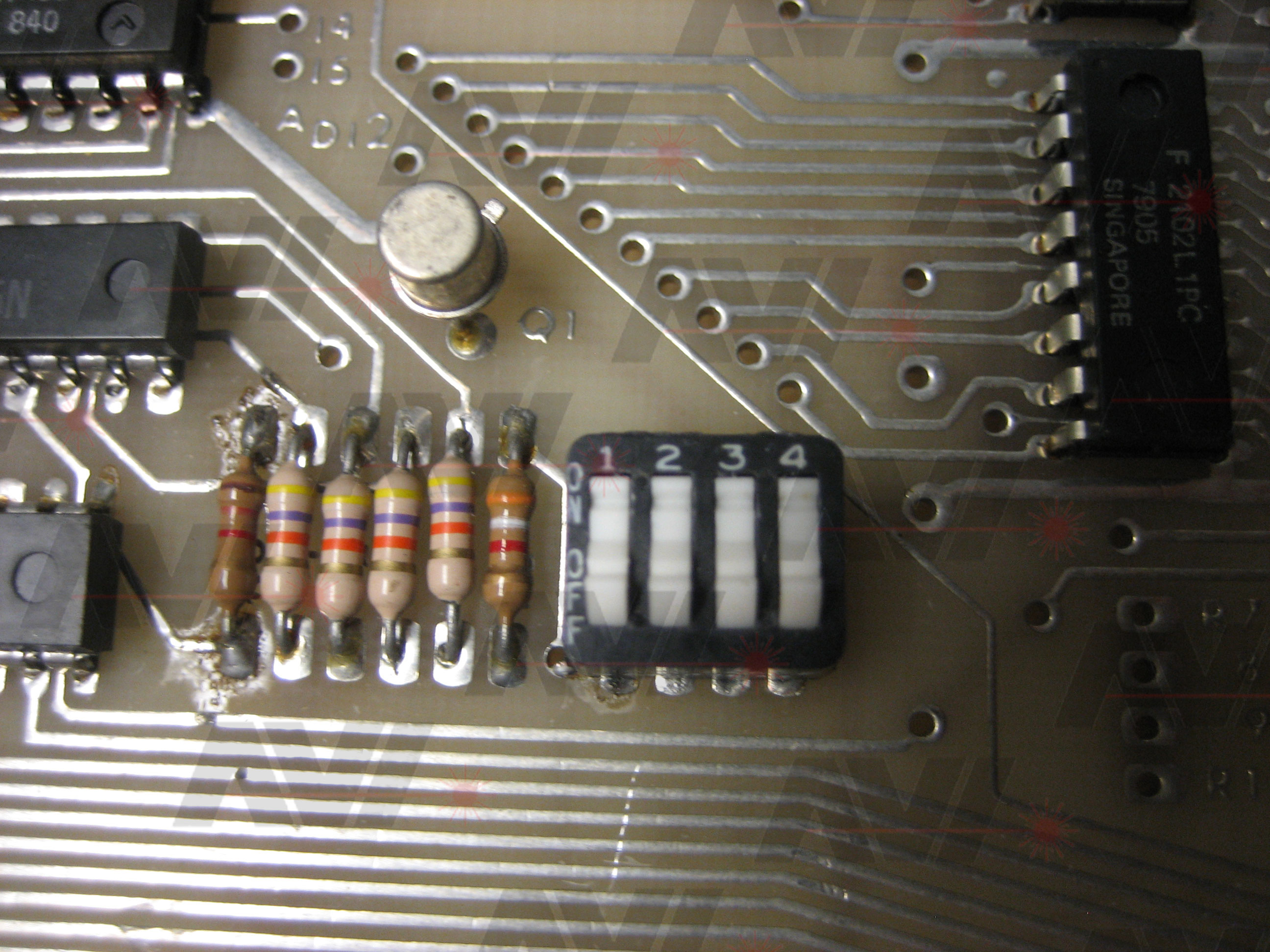
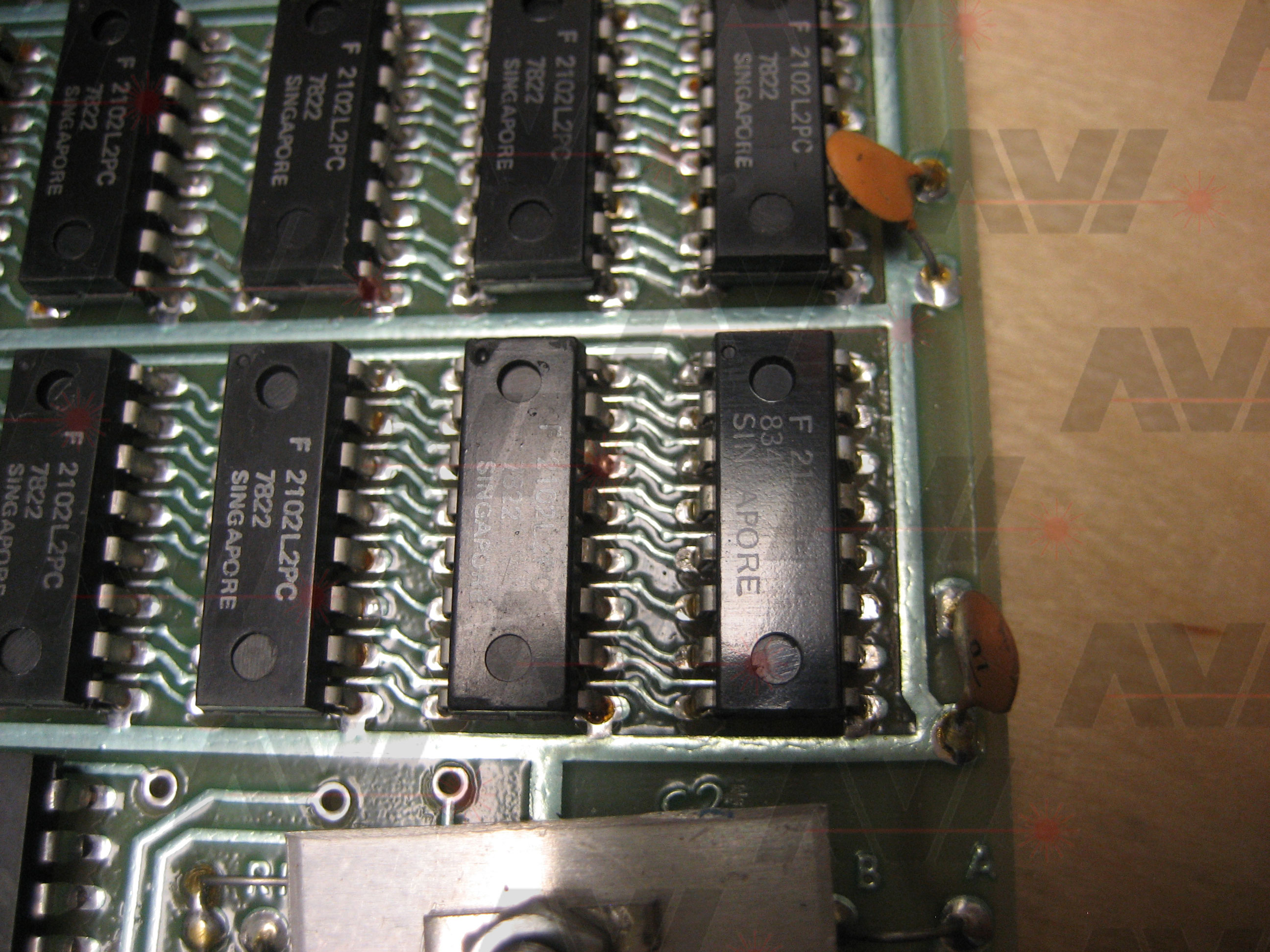
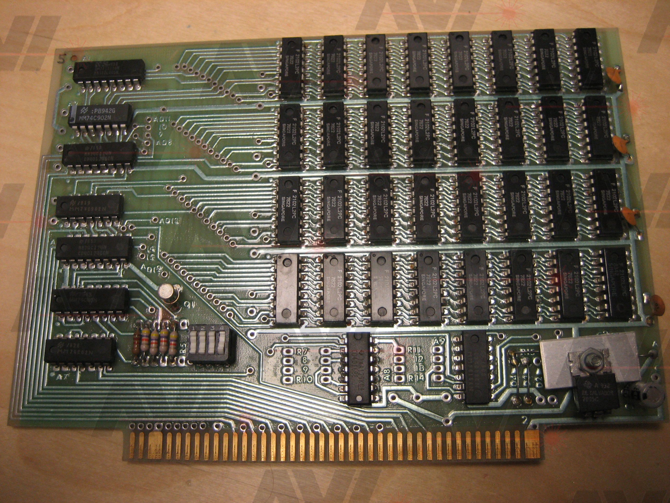
The RAM cards are laid out in a 8 x 4 matrix. Each row is 8 bits of 1K. The rows are addressed like this (when the "jumpers" are set to start at 0000h):
- 0000h - 03FFh
- 0400h - 07FFh
- 0800h - 0BFFh
- 0C00h - 0FFFh
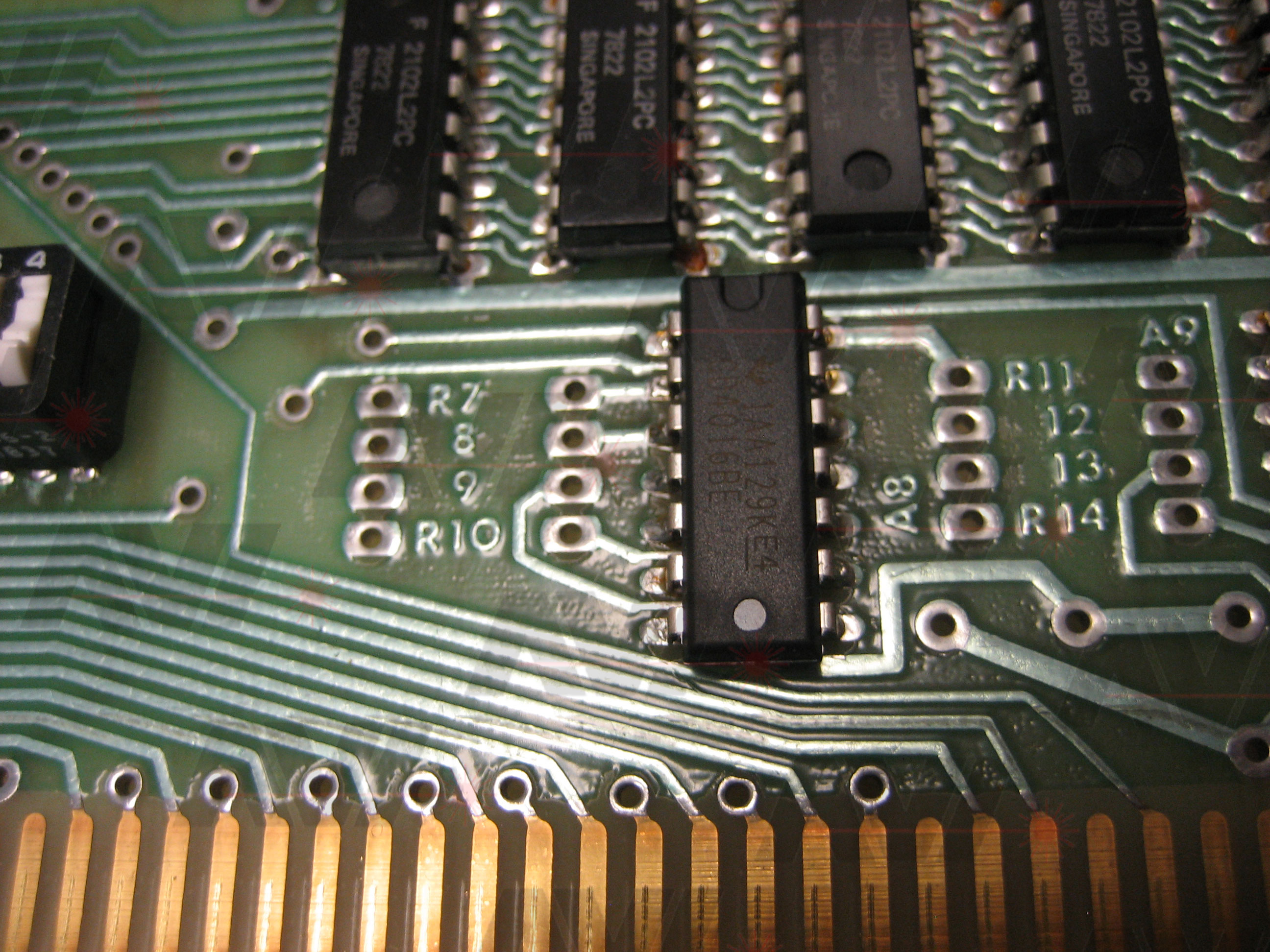
The columns are laid out LSB to MSB from left to right. The following picture shows the location of each RAM bank and the bit posistions. As I wrote before, the fluke displays address and data bits as 1-8 not 0-7.
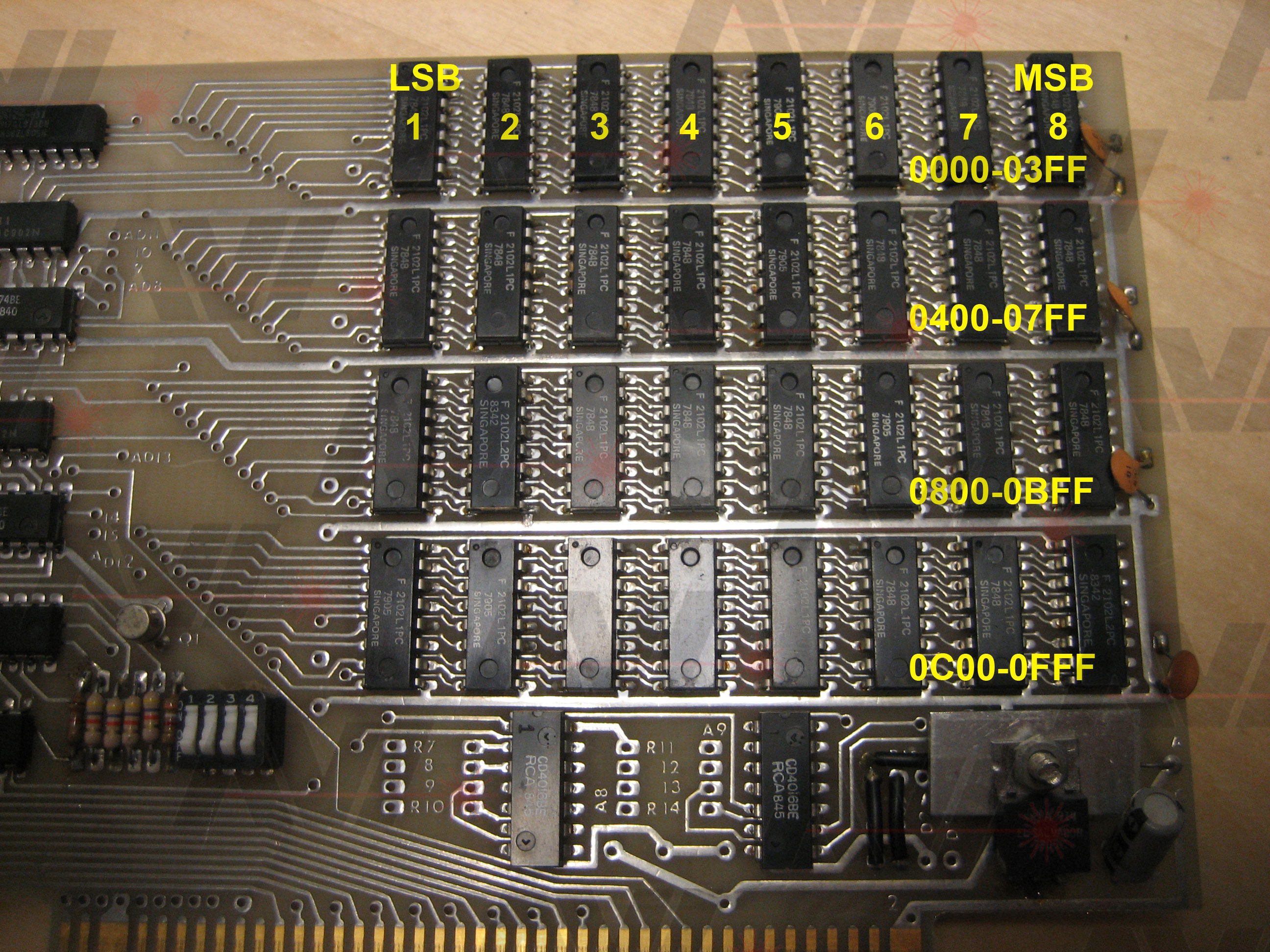
This layout made it easy to locate the possible bad chip. It would be on the third row in the second column.
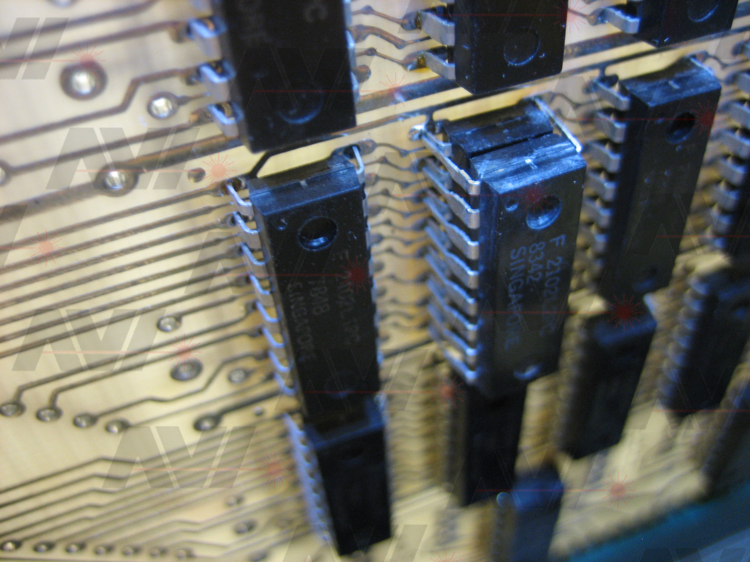
I verified that both of these chips were bad, one at a time using a trick from the arcade repair industry. I piggybacked a known good 2102 RAM chip over the suspect chips.
I re-ran the "LEARN" on the fluke but only on the 0800h - 0BFFh range. This time, while holding the good RAM over the bad one, the results were good with no errors reported.
Having confirmed that the 0800h chips was bad I replaced it. I then did the same with the 0C00h chip. When both chips were replaced, I re-ran the "RAM SHORT" test and found no errors.
I adjusted the "jumper" switches to test the board in all possible ranges. The decoder was working fine. RAM card 1 is now working as it should.
ELF 2 AND 4K RAM CARD 2
I installed the second RAM card and set it to the 0000h - 0FFFh range just like I did before. I installed the card, and once again the system did not work. The data bus was now stuck.
Using the fluke and oscilloscope, I found that one of the 4016 chips (used to control the direction of data to and from the RAM) was bad. I replaced the suspect chip and re-tested. The data bus was now okay again.
I did a "RAM SHORT" test and found errors that appeared to come from only one chip this time. It was located in the 0C00h-0FFFh range, bit 8. It would be the last chip on the bottom row, just above the regulator.
I removed the chip and installed a new one. I did the "LEARN" again over the full address range. RAM, with no errors, was found in the 0000h - 0FFFh range.
I then re-ran the "RAM SHORT" test and found no errors.
I adjusted the "jumper" switches on this board to test all possible decoded address ranges. The decoder was working as expected. Both RAM cards are now working.
ELF 2, BOTH RAM CARDS AND BASIC CARD
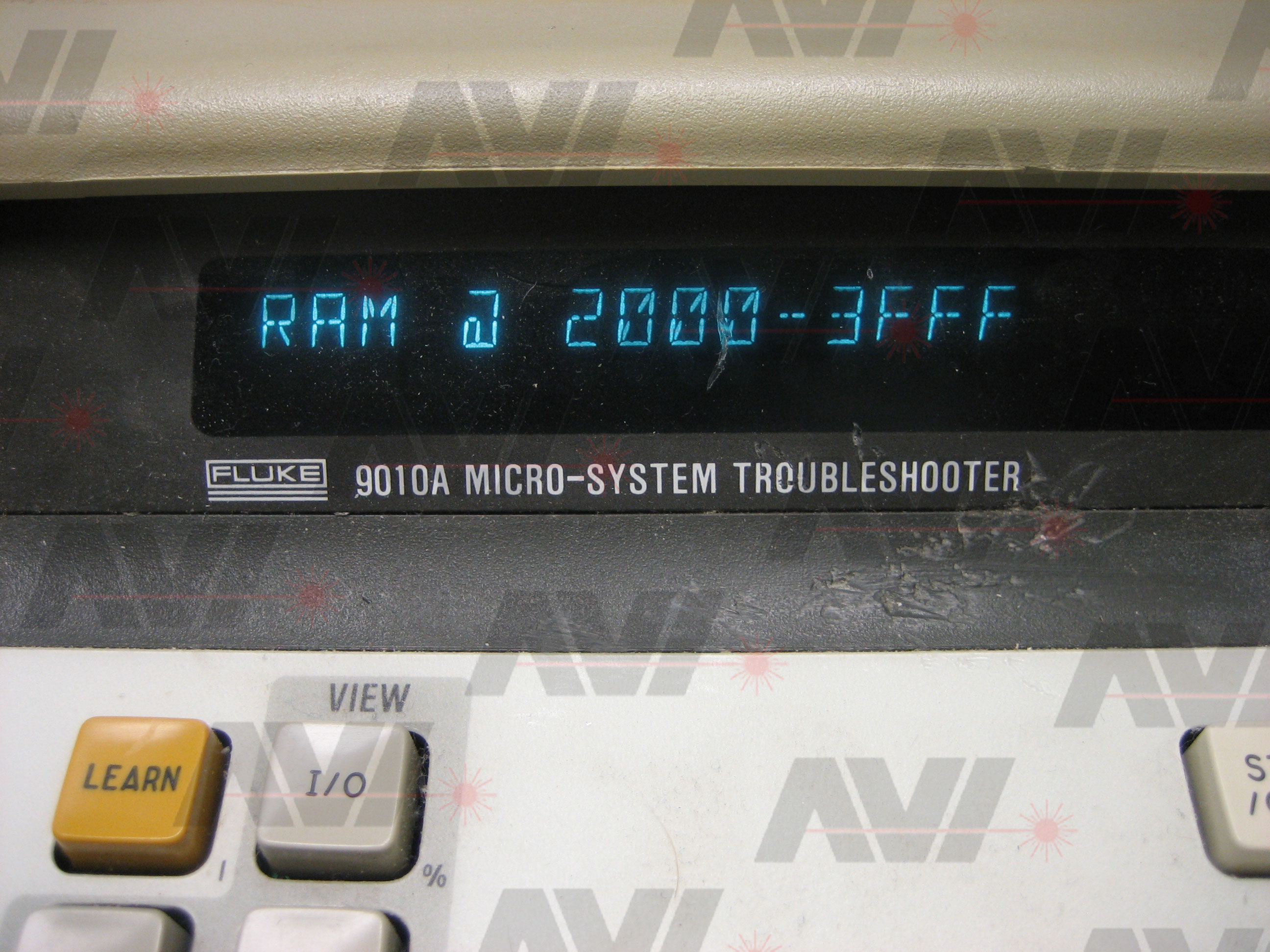
I set the address "jumper" switches to 2000h-2FFFh on one RAM card and 3000h-3FFFh on the second. For safety, I removed the mm57109 calculator chip while testing the Basic side of the Basic/Math card.
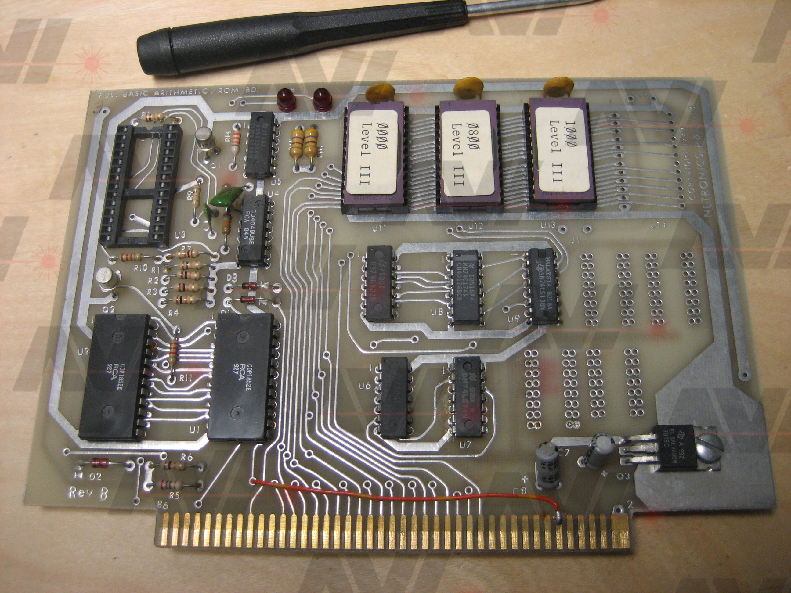
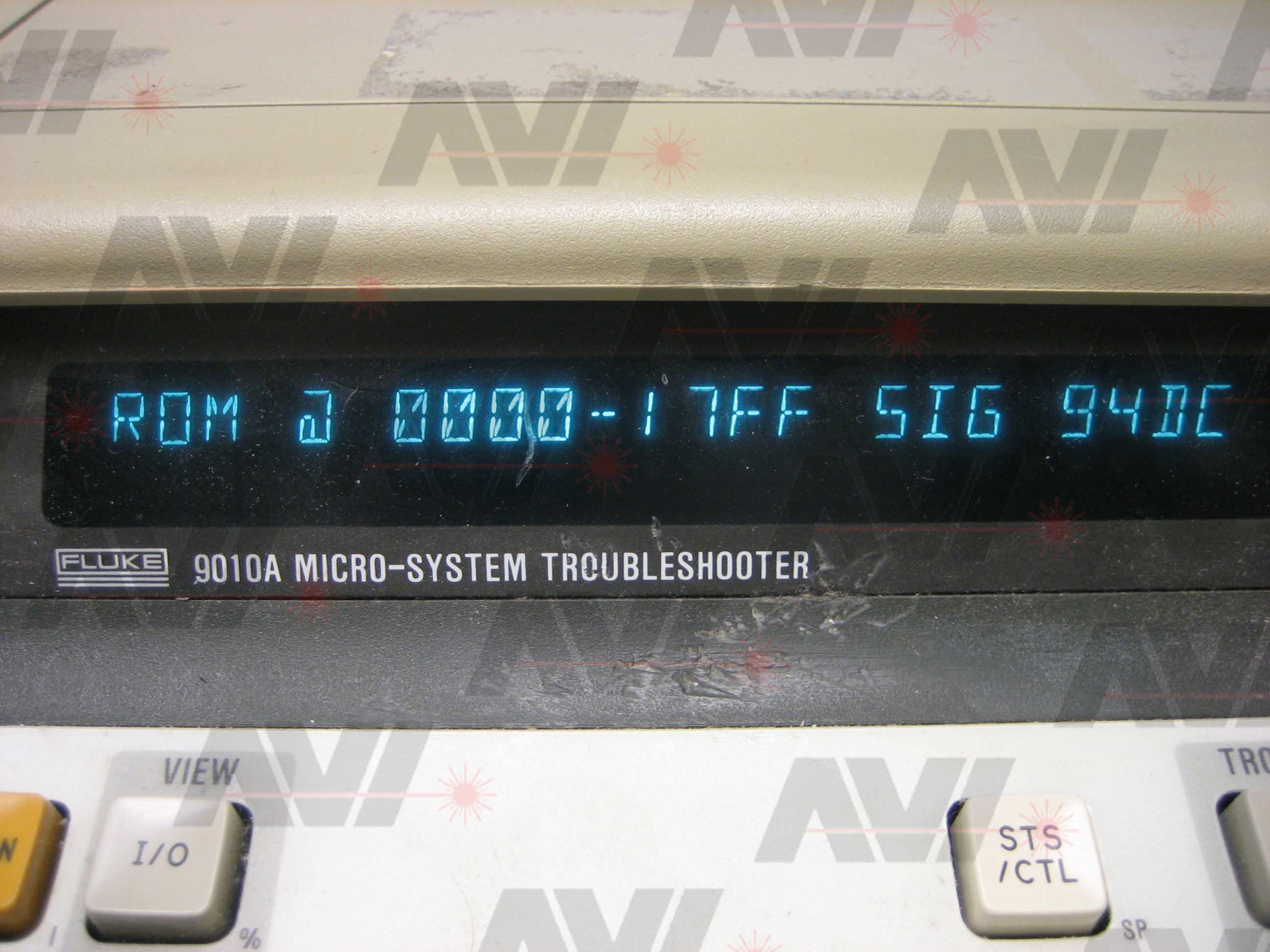
I removed the ROMs and dumped them also for safe keeping, all three ROMs read in fine, so I knew they worked. Plus I would have a backup of the code just in case something failed. I re-installed the ROMs. Using the fluke the I did a "LEARN". It found the basic ROMs at 0000h - 17FFh indicating the address decoder was working. It also found the two RAM cards from 2000h-3FFFh.
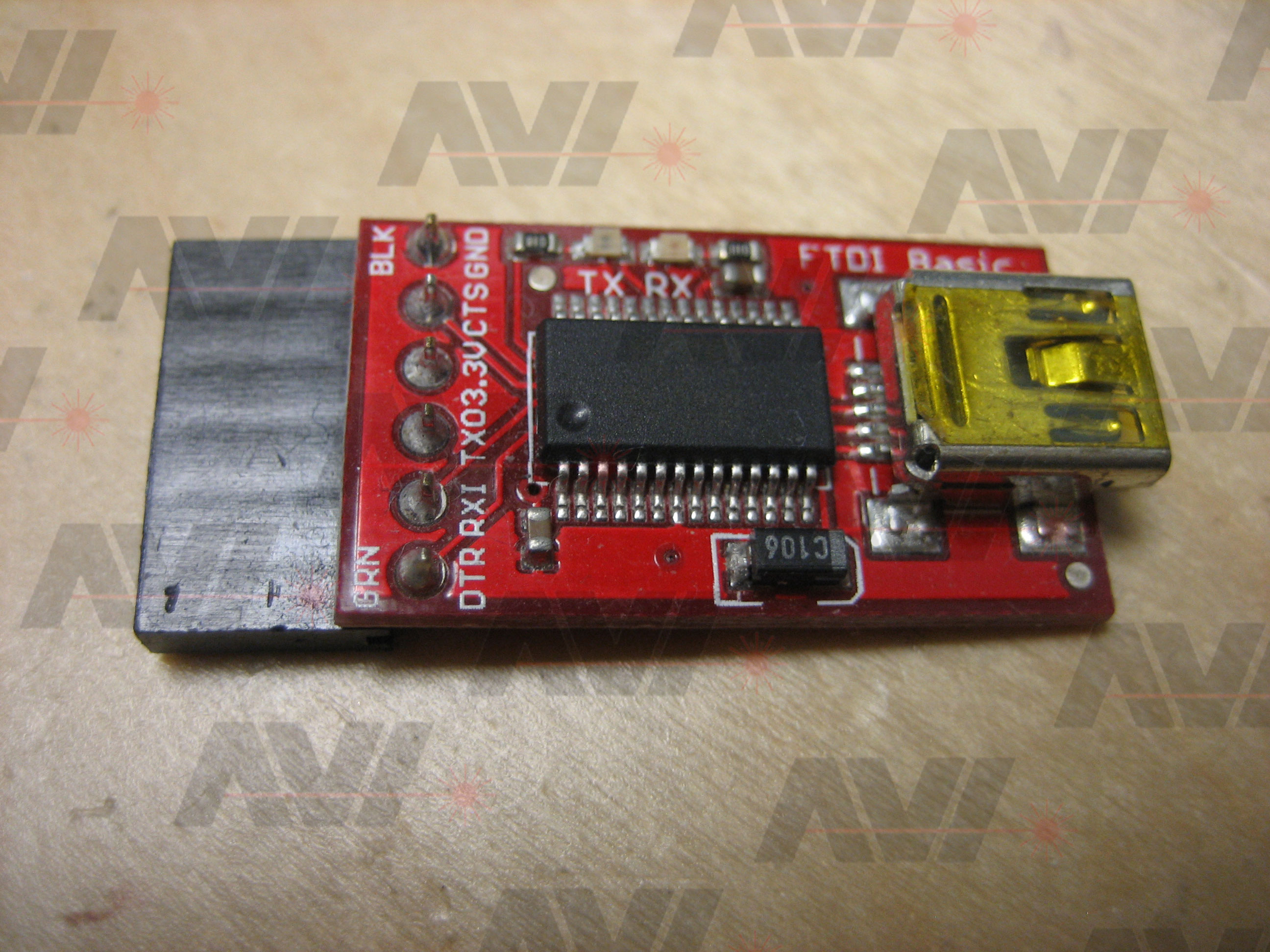
I connected a wire to the inverted "Q" line at the Q LED and another to pin 21 of the 1802 (EF4). I connected these wires and a ground line to a little Serial-to-USB board.
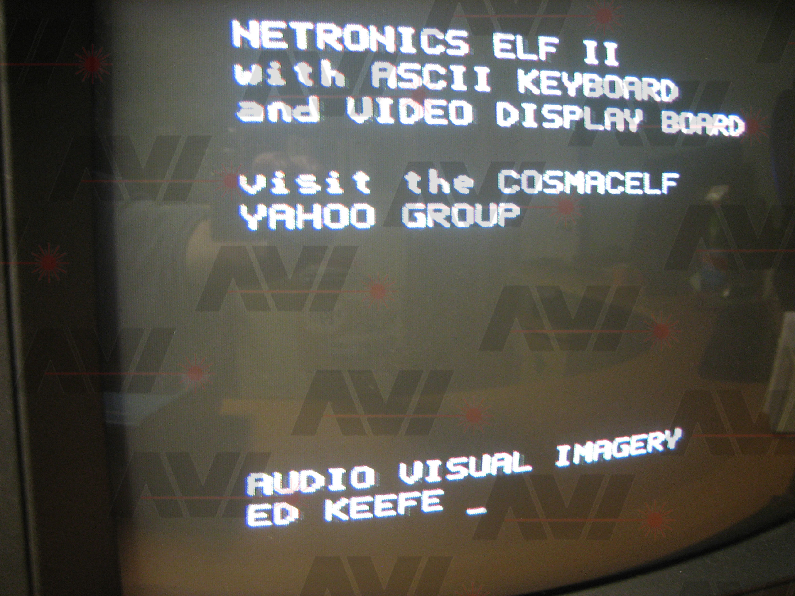
I started a terminal program on my PC. I set it for 300 baud, No parity, 8 data bits and 1 stop bit. When I powered up the system, I saw a few "noise bytes" in the terminal program. I pressed "Enter" and the system responded "WIDTH <32-64>?". I pressed "6" then "4". I got the following startup message:
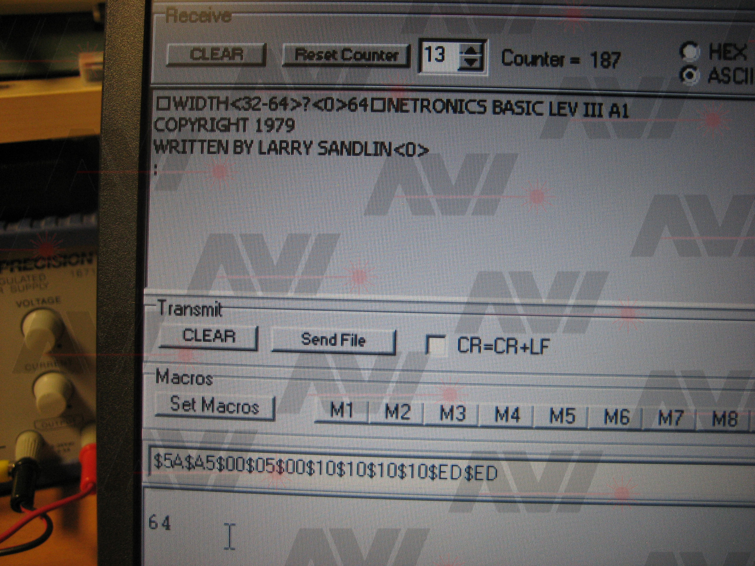
The Basic section of the board was working fine. I played around with Basic for a while as I had never seen it run on an Elf II before.
ELF 2 AND GIANT BOARD AGAIN
Now that I had the basic portion of the basic/math card working with the ftdi board, I tested the rs232 circuit on the Giant board.
I pulled out a second power supply so I could add the required -8 volts.
With both power supplies ready, I applied power and entered 7B 7A 30 00. This short program would quickly blink the Q line. I used the pulsing "Q" line to generate a signal that the rs232 circuit would level shift. I looked for a negative going pulse each time the Q line activated. I saw that the pulse was level shifting correctly.
I wired up a DB9 connector to the pins of slot 5 dedicated to serial TX and RX from the Giant board.
Using an old laptop I have, that has a compliant rs232 port, I connected a serial cable and ran the terminal program, nothing. Of course I had the TX and RX line backwards, fixed it a Basic started again. I played with Basic again for a bit using the rs232 serial connection. I did a "PR BYTE" in Basic and it printed out the available RAM.

The system was now working with all of the cards installed using an rs232 connection. All that was left was to test the rest of the functions of the Giant board and the calculator chip.
ELF 2, BOTH RAM CARDS, BASIC CARD AND CALCULATOR CHIP
Before installing the calculator chip, I tried a couple of math functions. I tried to do "PR PI#" and got a condition 2889???? message. I then tried to do "PR 10#5+" and got the same message.
The math functions in Basic are used in RPN format. For example, to add 3 + 4 in Basic you would type "3#4+". This equates to pressing "3 Enter" followed by "4+" on an HP calculator. It is weird at first but make sense after a while.
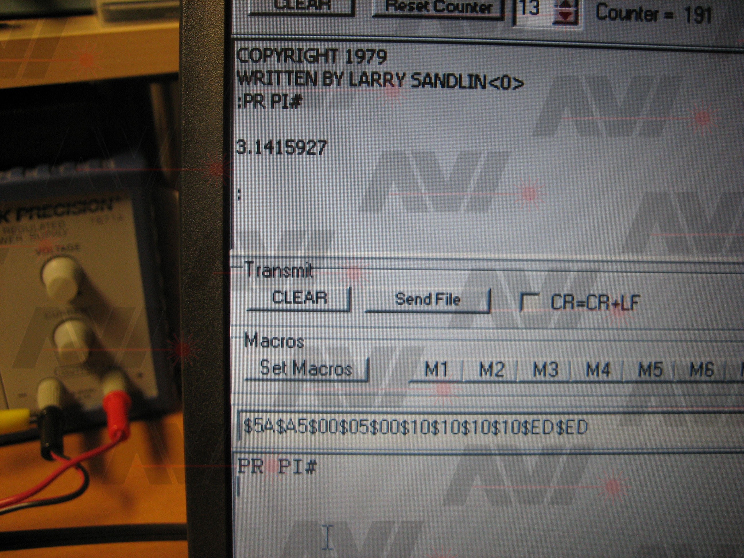
I powered down the system and installed the MM57109 chip. The calculator chip also needs -8 volts to operate. So with both power supplies, I powered up again and after the width and startup messages, I tried the "PR PI#" again, this time I got 3.14...
I tried a couple other math functions:
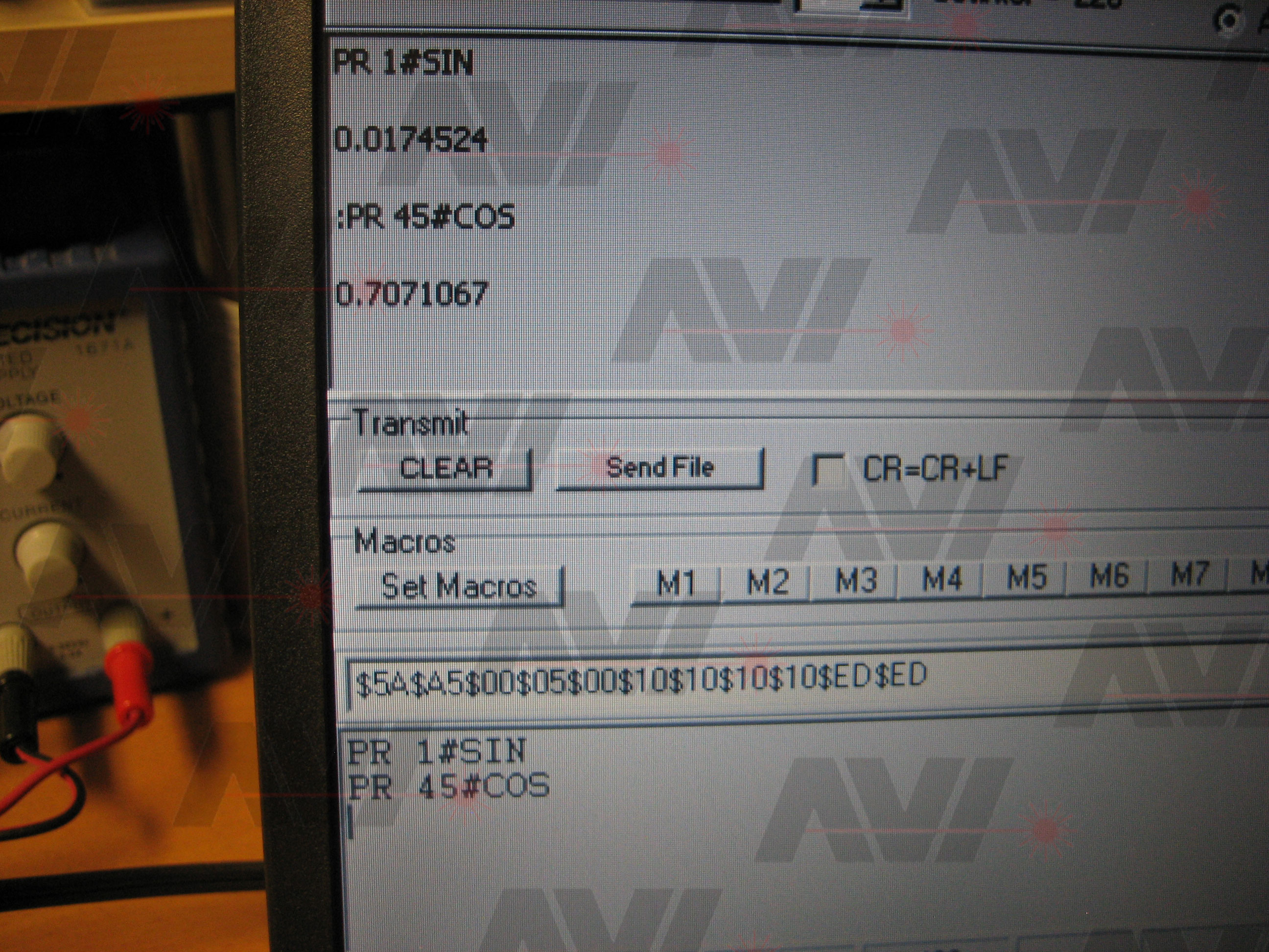
I then wrote a short program that counted from 1 to 255, on each pass it would display the current count and the count multiplied by PI. It ran fine without error. The Basic/math card was working without any rework.
ELF 2 AND GIANT BOARD AGAIN
I tested the 1853 N-Line decoders next. Going one output or input at a time, I tested each line. They all worked fine.
I then tested the tape circuit. The output section had no output. I looked for "Q" signals on the LM3900. I saw it at the input, but very faint on the output of the LM3900. Without testing the input side of the LM3900, I replaced it.
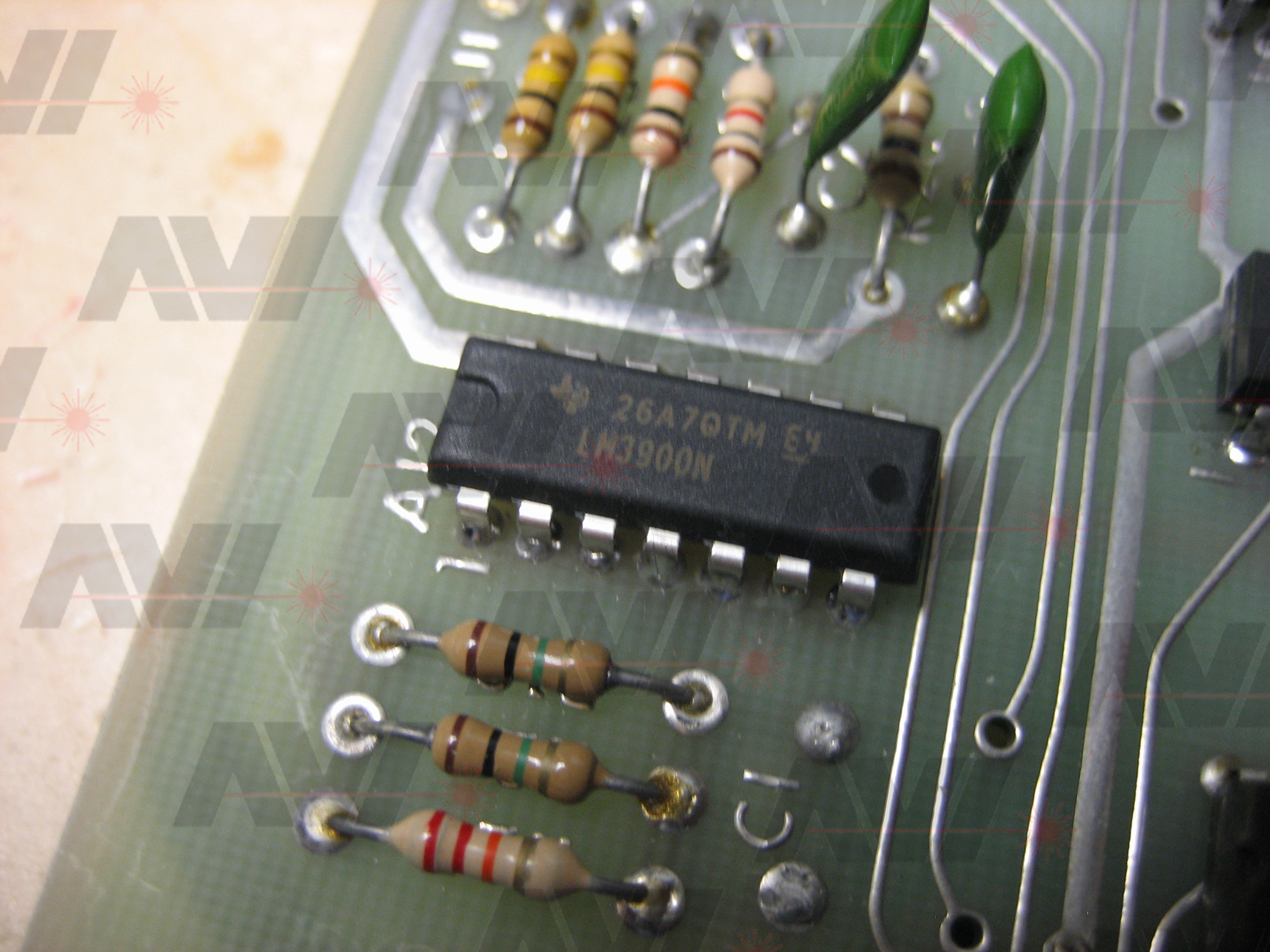
After replacement of the chip I had a good output signal. I entered a short program and saved it to my little voice recorder. I checked to make sure it recorded and sounded right. It did. I loaded the file back into the system and ran it with no problems.
All that was left to test on the Giant board was the I/O ports. I entered "67 00", flipped RUN, and checked to make sure all the output lines were low. All the line checked as low. I then entered "67 FF" and checked for all output line to be high. Once again, all lines checked out fine. One at a time I tested each output line by activating a single line at a time using 01h, 02h, 04h, 08h, 10h, 20h, 40h and 80h as the data after the OUT 7 command (67). I got the correct result each time. The output port was working fine.
The input port was tested in a similar way. I read in the port by "latching" the data into the port with a jumper wire to 5 volts. First, I tested for 00h because the inputs are pulled low. One by one I moved a jumper wire, connected to 5 volts, to each input line. Using the other jumper wire I would latch it into the port. I read the port after each wire move and latch, making sure each bit was not shorted. All lines checked out fine. The input port was working fine.
The Giant board is now fully working
The entire ELF II system with Giant Board, 8K of RAM and the Basic/math card was working completely. I put the Elf II aside for a bit and started testing the ASCII keyboard and Video Display Board
THE ASCII KEYBOARD AND VIDEO DISPLAY BOARD
I had never seen a Netronics keyboard in person before, so I did not know what to expect. I cut all the wires connecting the board together and to the blue metal case. I then removed both boards so I could test them individually.
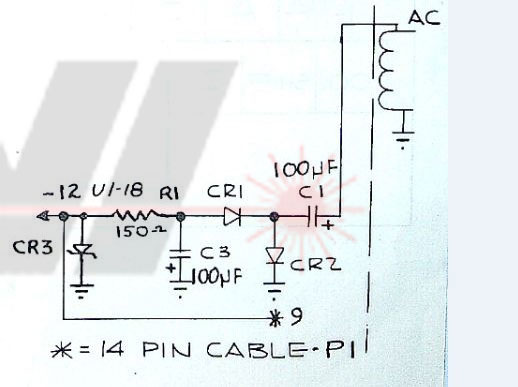
I was not exactly sure how to hook the keyboard PCB up. I did not see a 5 or 8 volt connection on the PCB, only an AC connection which feeds this circuit:
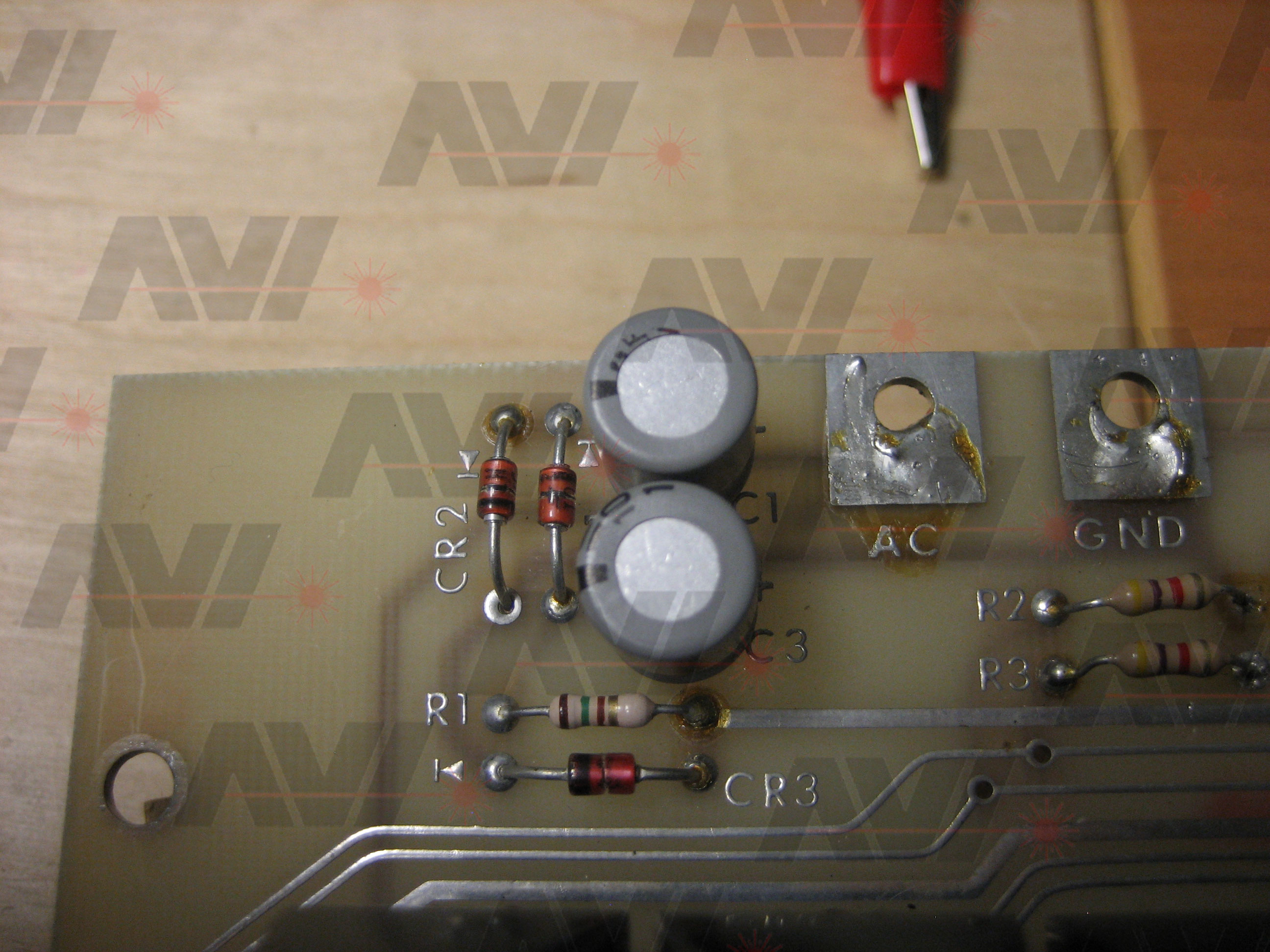
I have a schematic of the 2 chip keyboard and the video display board. The keyboard schematic I have does not have this diode circuit, but it does have two voltage regulators. Also, I did not know what the jumpers on the keyboard and video display board were used for. I made a post in the Yahoo group named "cosmacelf". A few people offered to help me out with documentation.
AN ASIDE
If you are not a member, and are interested in anything 1802/Elf/VIP/COSMAC related, you should consider becoming one.
I am thankful for responses from Glen Roger and Paul Backhouse. I got a copy of the Video Display Board assembly and instruction from Glen. Paul Backhouse uploaded a bunch of old Netronics documents, including the schematic for the single chip keyboard, to the cosmacelf group. He also painstakingly transcribed the documentation for the Netronics FastVid board.
Thank you is in order for Glen and Paul, and also to everyone in the group.
BACK TO THE KEYBOARD
Before seeing the single chip keyboard documents, I did not understand the -12 requirement. Now I see that it is generated right on the keyboard PCB, by grounding one side of the AC input and using a zener diode the -12 volts is created for use by the KR2378 chip.
Following the check out steps from the Netronics documentation, I connected an AC transformer. I only had a 9VAC transformer. It should be 6.3 to 8vac, so it is a little high. Before applying power, I checked to make sure I could still find a replacement for the zener diode if it was dead or I killed it. I removed the KR2376 keyboard encoder chip and tested for -12 volts at pin 18 of the encoder chip. I found a good -12 volt signal there. I replaced the KR2376 chip to its socket.
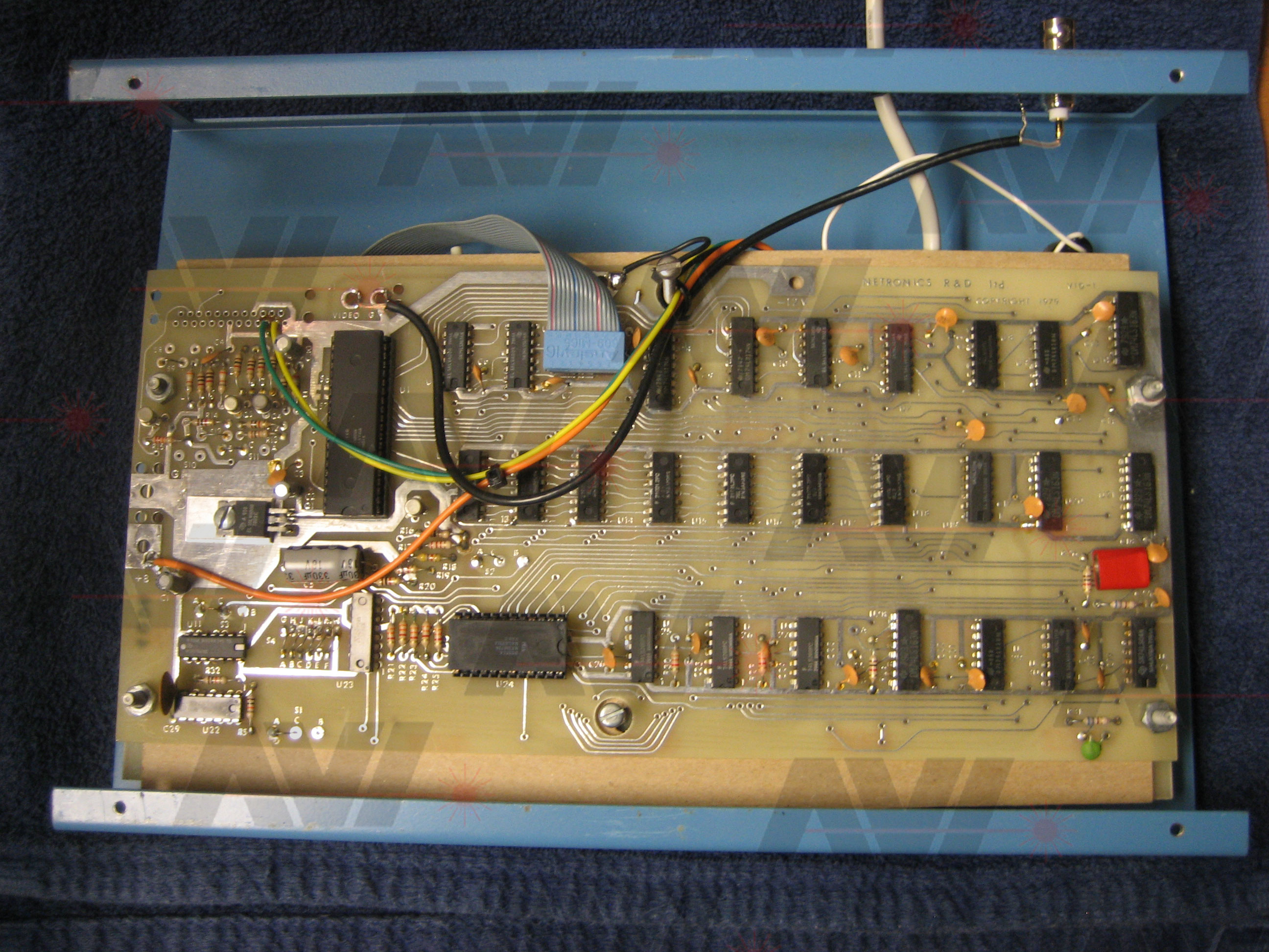
THE VIDEO DISPLAY BOARD
I inspected the board looking for obvious problems like shorted wires or dirt on the PCB. The board was in good shape.
When I had cut the wires to the board, I left the two serial lines a little longer. I soldered these together to form a loop-back. This would allow me to test operation of the serial section of the video display board.
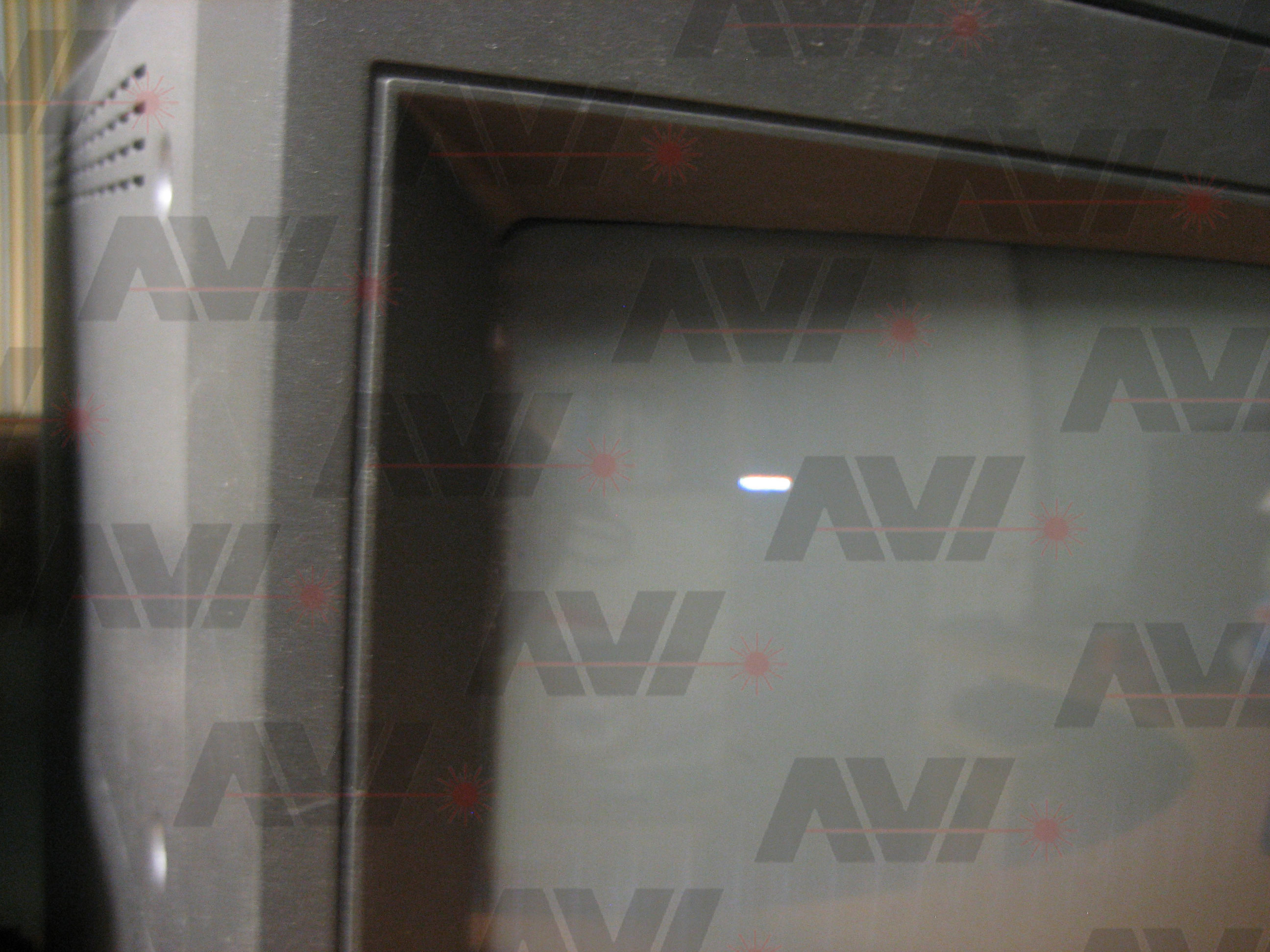
I connected a video monitor and applied 8 volts to the board. I powered it up and the screen was full of junk at first but the board cleared the display and I was left with a cursor. It was clear and steady.
With the confidence I gained from reading the old Netronics documents, I connected the keyboard and the video display board. Once again I got a cursor. I typed each key and each time it responded with the correct character on the screen. The only exceptions were the "=/-" and "C/c" keys. These two keys were not responding as they should. Depending on how hard and what angle I pressed them I would sometimes, but not always get a response.
Using the Netronics programmer as a source of parts again, I replaced the two bad key switches. Now these two keys work as good as the others.

Together the keyboard and video display board were acting as a simple 300 baud serial terminal.
I determined how many wires I would need to connect the terminal with the Elf II. I would need 5 wires.
One of the anomalies of the keyboard I received was, a previous owner of it had added a single push button switch to the case. At first I did not understand why. They had it connected to the input key.
On page 4 for the Netronics Full Basic Level III manual, under "SPECIAL CHARACTERS", the following is written:
"Depressing input (EF4) key on your ELF will suspend program execution and listing returning the program to the command level."
I would need to add another wire back to the input switch on the Elf II PCB for a total of 6 wires.
Using the cable from a DB-9 serial cable, I made the required connections. I re-installed the keyboard and video display board in the blue metal case. I made a mating cable and wired it to DC and AC power. I shorted the TX and RX lines and made sure the entire terminal still worked which it did.
I disconnected power, separated the serial lines and installed the mating section of cable to the Elf II. I added a cable to get power into the Elf II.
When I received this system, an old owner has placed three paper stickers on the Elf II metal case.

I carefully removed them. To get the remaining adhesive off I was going to need a weak solvent. On a portion of the case that would be hidden when the case was closed, I tested a small area using 91% isopropyl alcohol. It had no effect on the blue finish of the case. Using just a small amount of alcohol, I was able to remove the stickiness left behind by the stickers. The case was now ready for use.
I cased up the Elf II and made sure it powered up correctly. I connected the terminal and Elf II together again. I powered up the system and started up Basic using the terminal. Everything came up as it should.
BASIC/MATH CARD AGAIN
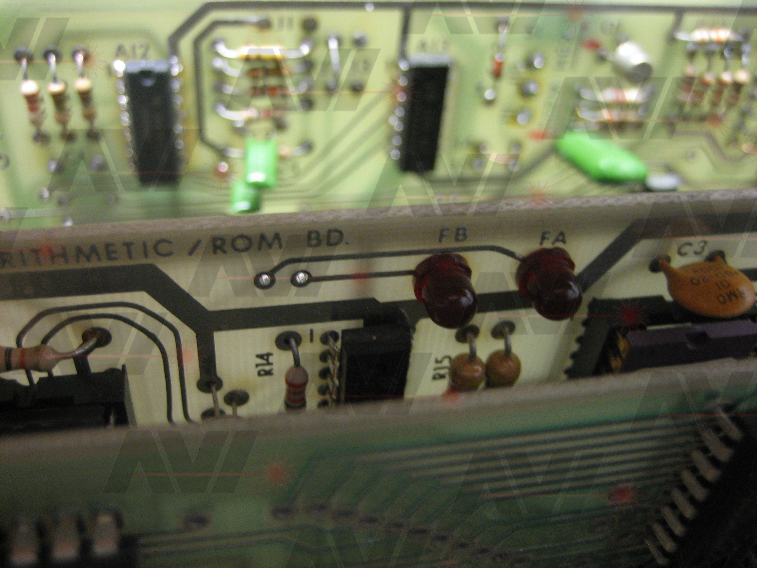
I realized that I had not tested an optional feature of the Basic/math board. An old owner of the card installed the two optional LEDs. These LEDs are controlled by issuing a "PR SF1#" or a "PR SF2#" command. Each of these commands will light one of the LEDs.
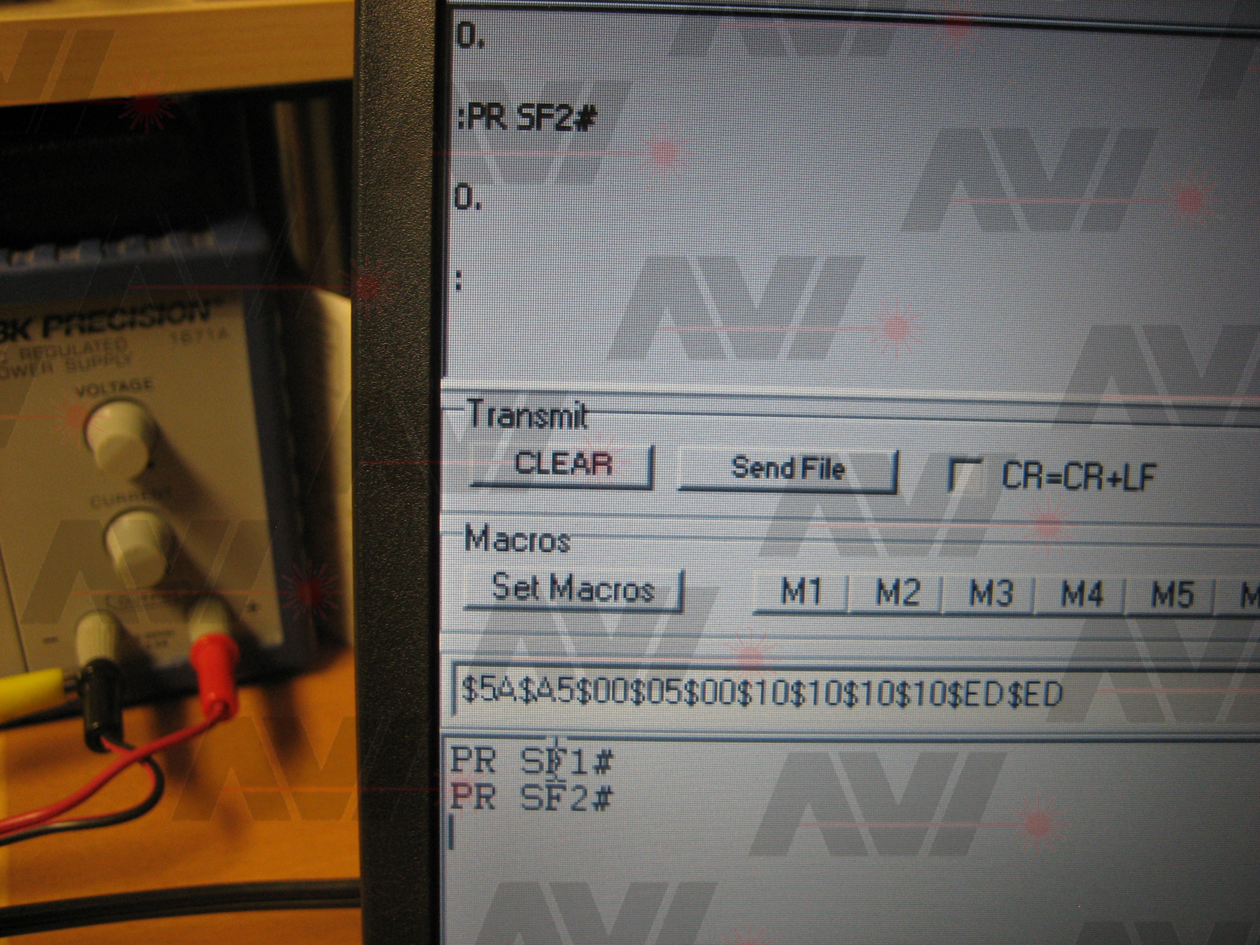
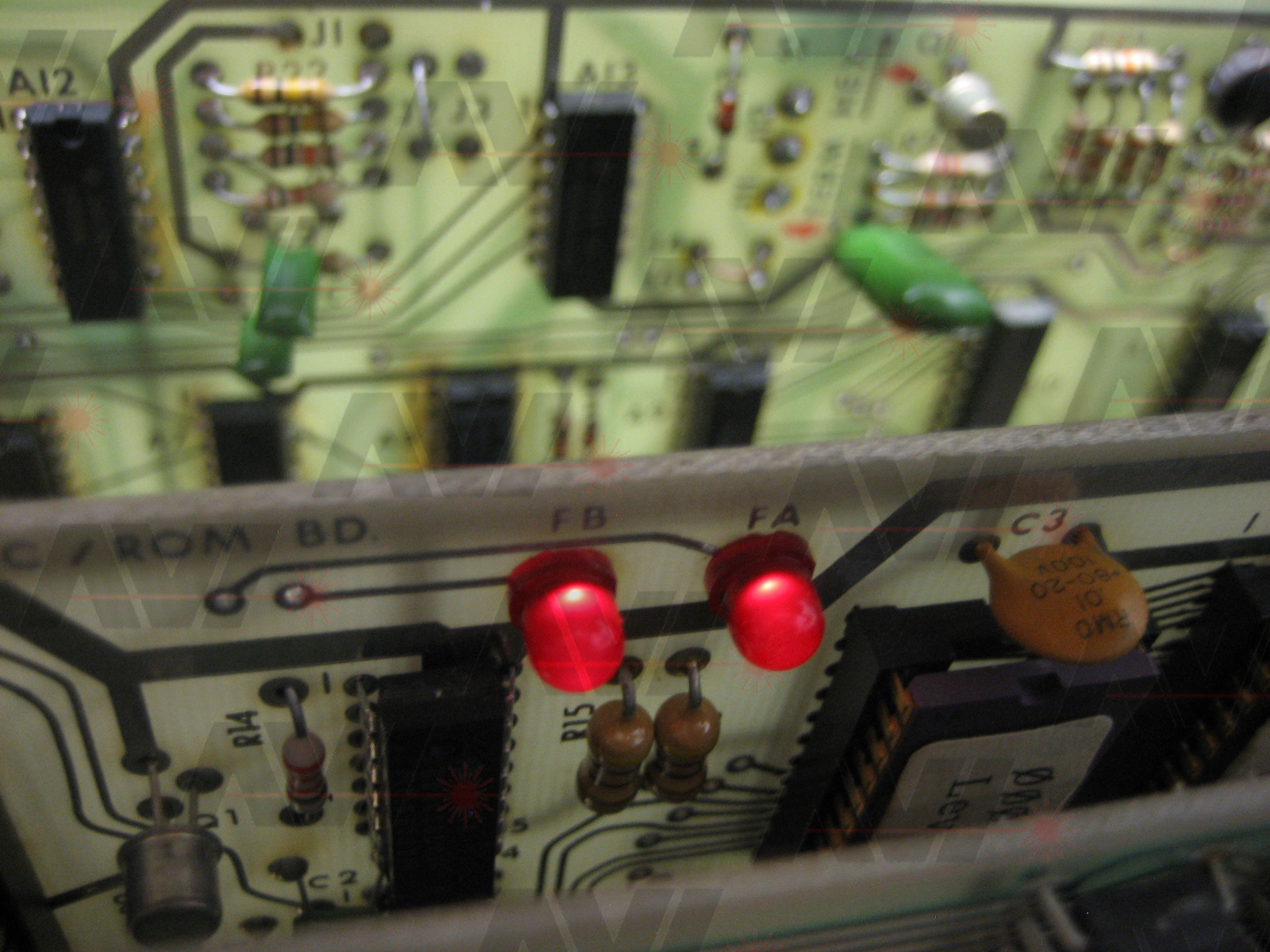
The LED are driven by the calculator chip itself. When one or both of the LEDs is lit, the only way to turn them off that I have found is to do a "PD CL#" command which is the "CLEAR" command for the calculator chip.
That's it. I have the system working as it should and I am happy with how it turned out.
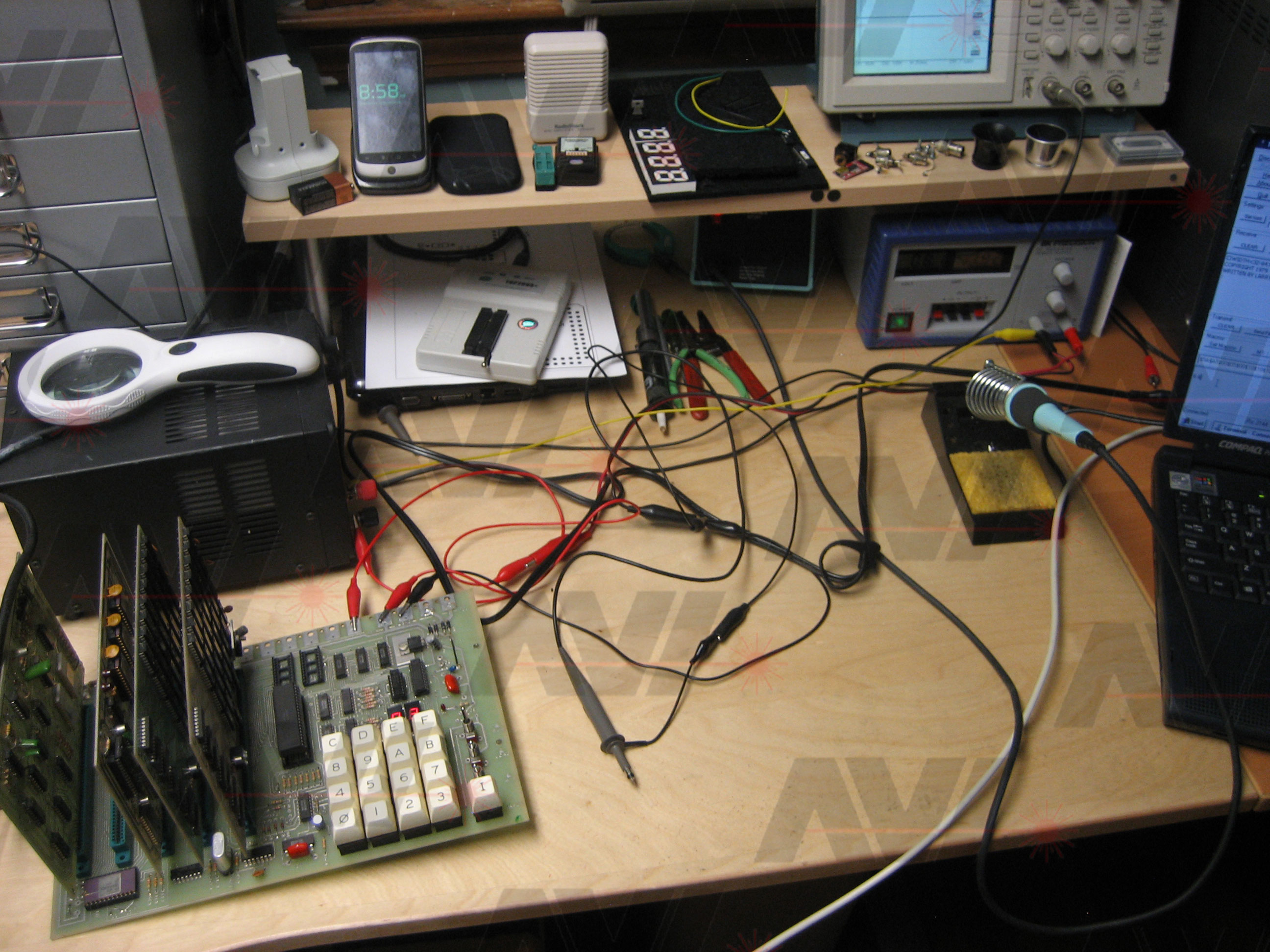
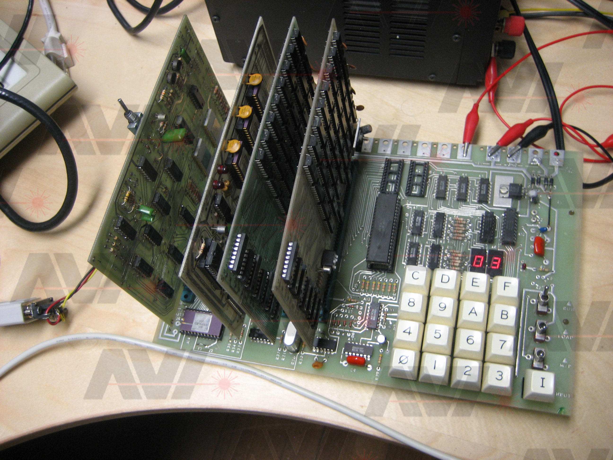
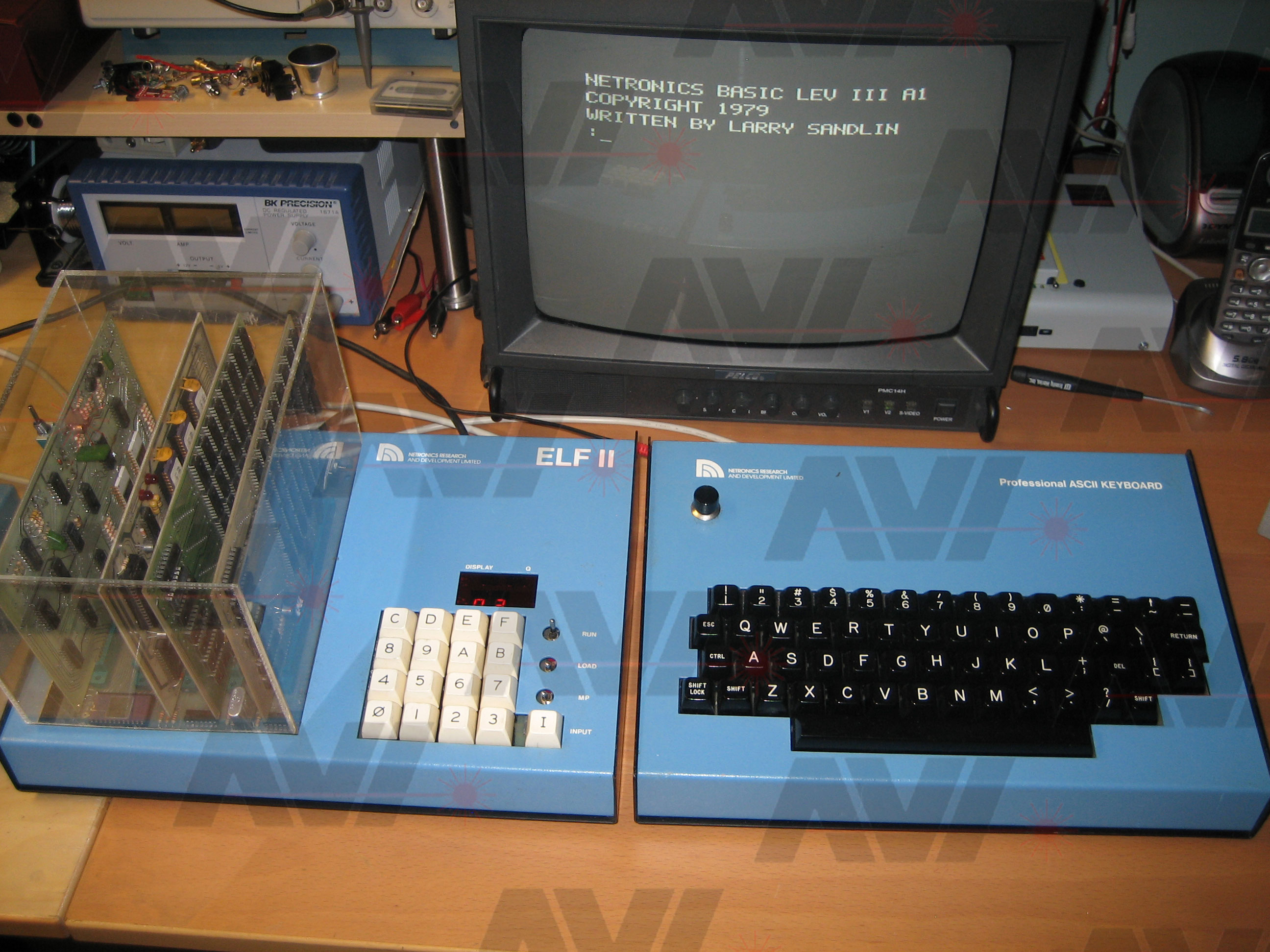
Here is a picture of the complete system without flash.
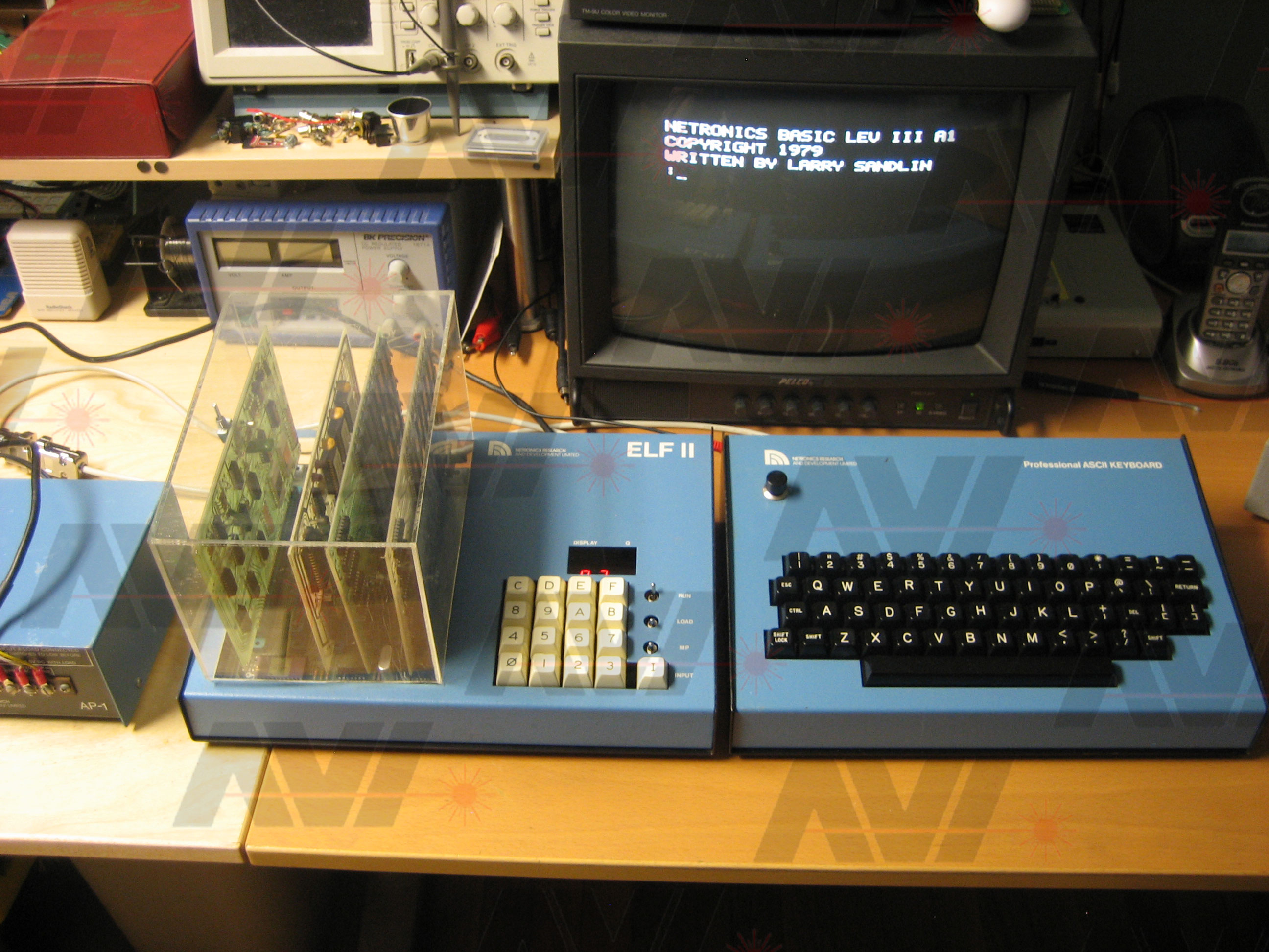
Here is a picture of the complete system with flash.
I hope you found this interesting.
ED
Please feel free to contact me at the e-mail address in this image: