
COSMAC VIP II
I attended a computer show in Boston, MA in the early 80's. At the time I was really into the RCA COSMAC VIP. I could not wait to see the newest hardware and software in person. Everything was kind of out of my price range at the time (I was still in high school). I had built a bunch of expansion cards. I even built a couple of robots that were controlled by the VIP. I had also built a robotic arm for my school's science fair. I made it to the state level with it. It could detect and remove defective items from an assembly line.
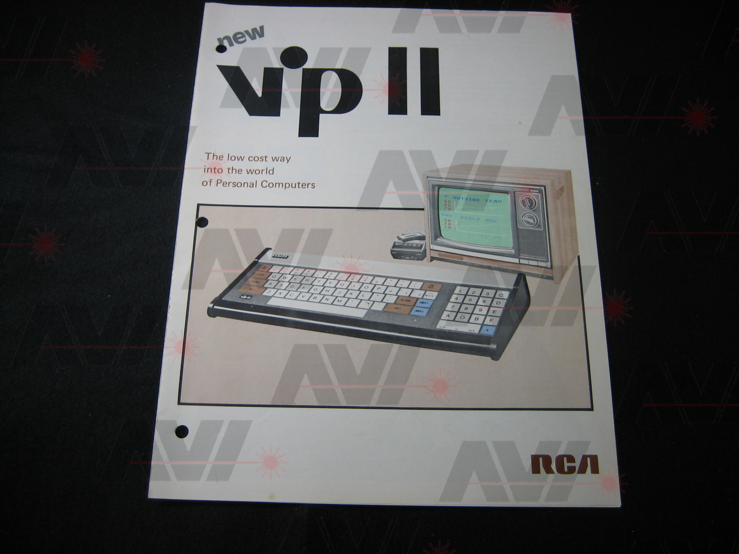
While at the show, in the RCA booth, one of the items caught my eye. It was the new VIP II computer. It was just a prototype, but I was impressed. It was supposed to be released later that year. I asked a bunch of questions and learned a lot about it. Simply put, I had to have it.
It was never released.
The only remnant of it I had was the simple bi-fold brochure I had received at that show.
In the past few years my interest in the COSMAC VIP has been re-kindled. I was going through some of my old VIPER magazines and found an ad for the VIP II.
That issue is available here: VIPER, Volume 2, issue 3, Pages 26-27.
The complete collection of VIPER issues are available here: mattmik.com
It listed the specs for the device. That got me thinking about that brochure. I dug through my COSMAC stuff and found it. I looked through it and remembered how I used to read it over and over back when I was a kid.I scanned the document, put it on my PCs desktop and put the original away. Here is a photo of that brochure.
I was looking at the list of statements the VIP II had available and noticed that it looked a lot like the Floating Point Basic RCA had released for the original VIP. I used to have it. I remember it needing a fairly well expanded VIP.
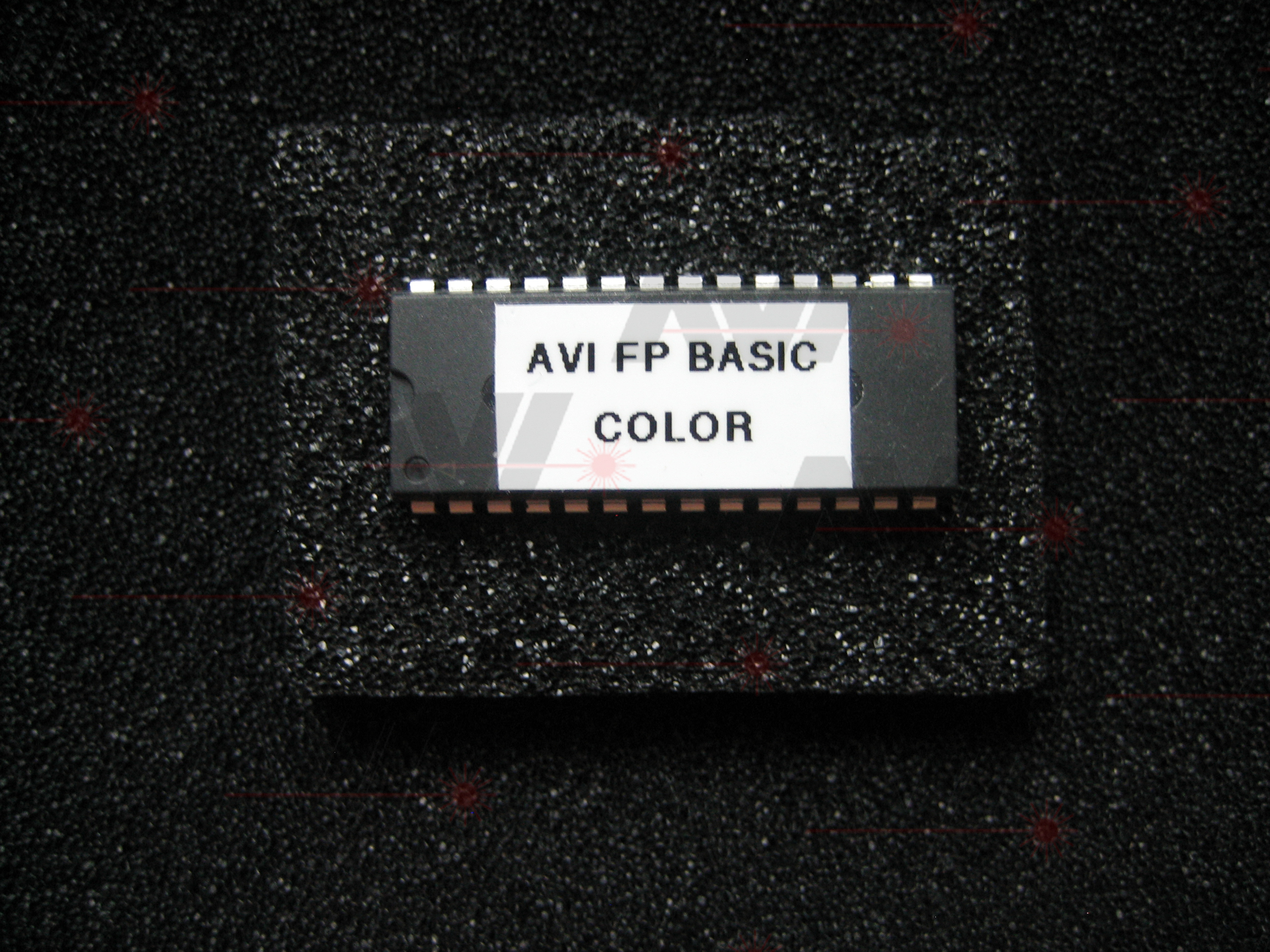
I went through all the boxes of 1802/COSMAC stuff I had and found my original copy of the Floating Point Basic tape and manual. Here is a photo of it:
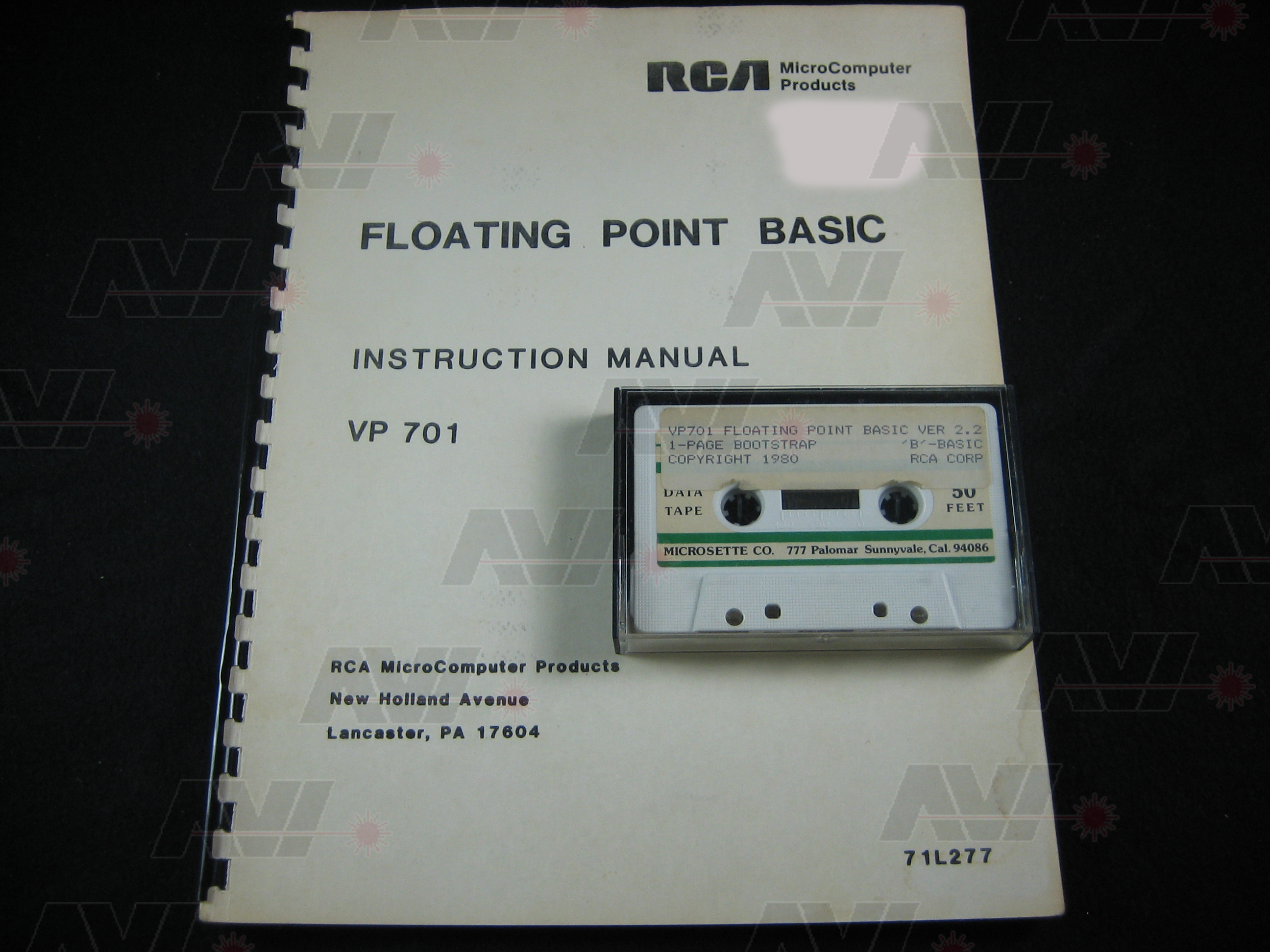
My old address was on the front of the book, so I grayed it out.
Reading through the manual it said that at least 20K of RAM was needed to load it. Back in the day I used a 5 port expansion board with 4 - 4K RAM expansion boards. I didn't really want to hook all that up. I still have them though, just didn't want to have to debug it.
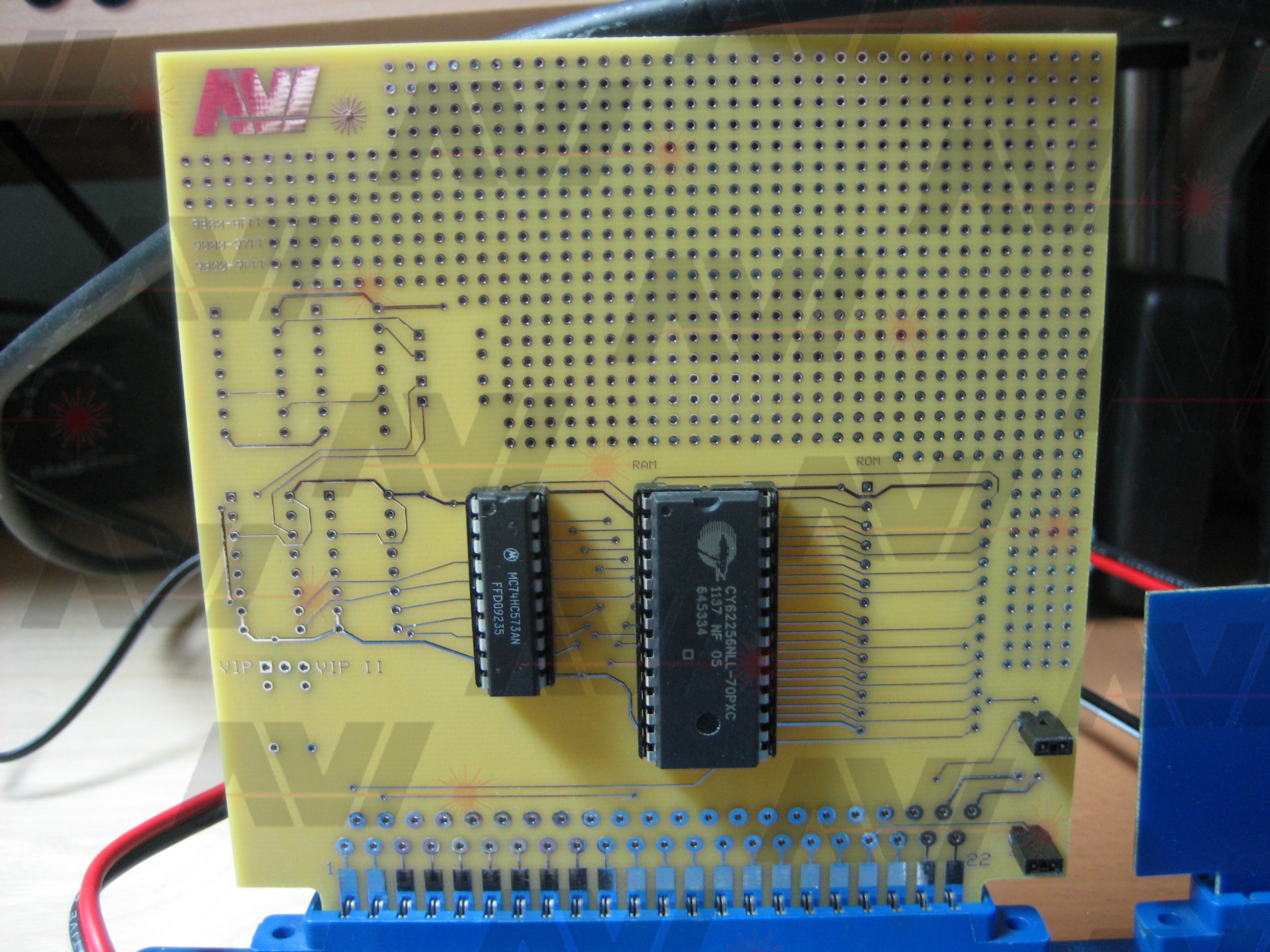
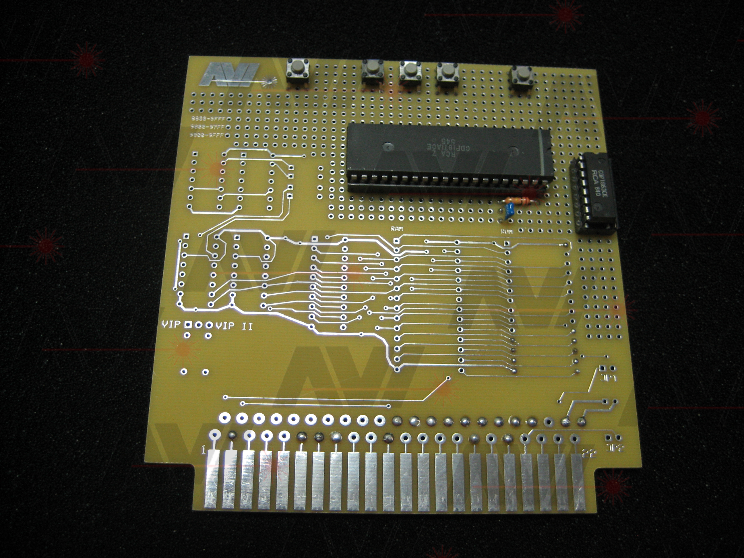
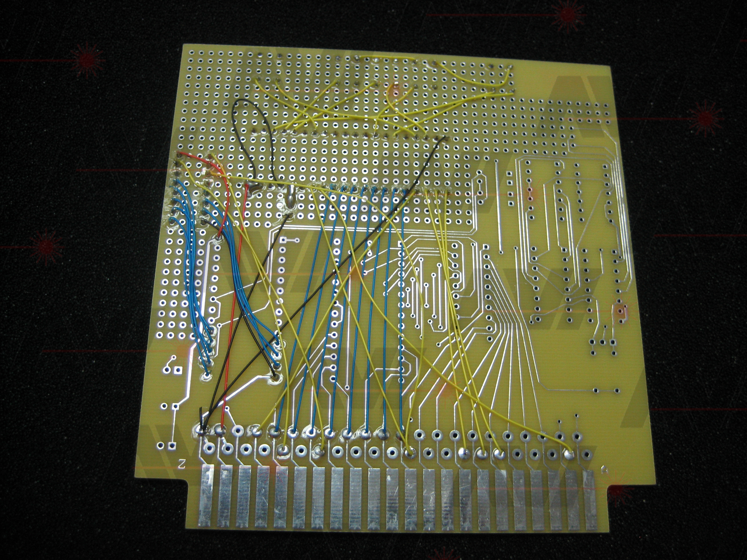
I decided to put a RAM board together. I decided to use a single 32K by 8 static RAM chip, the 62256. I used a 74HC573 to latch the high address bytes.
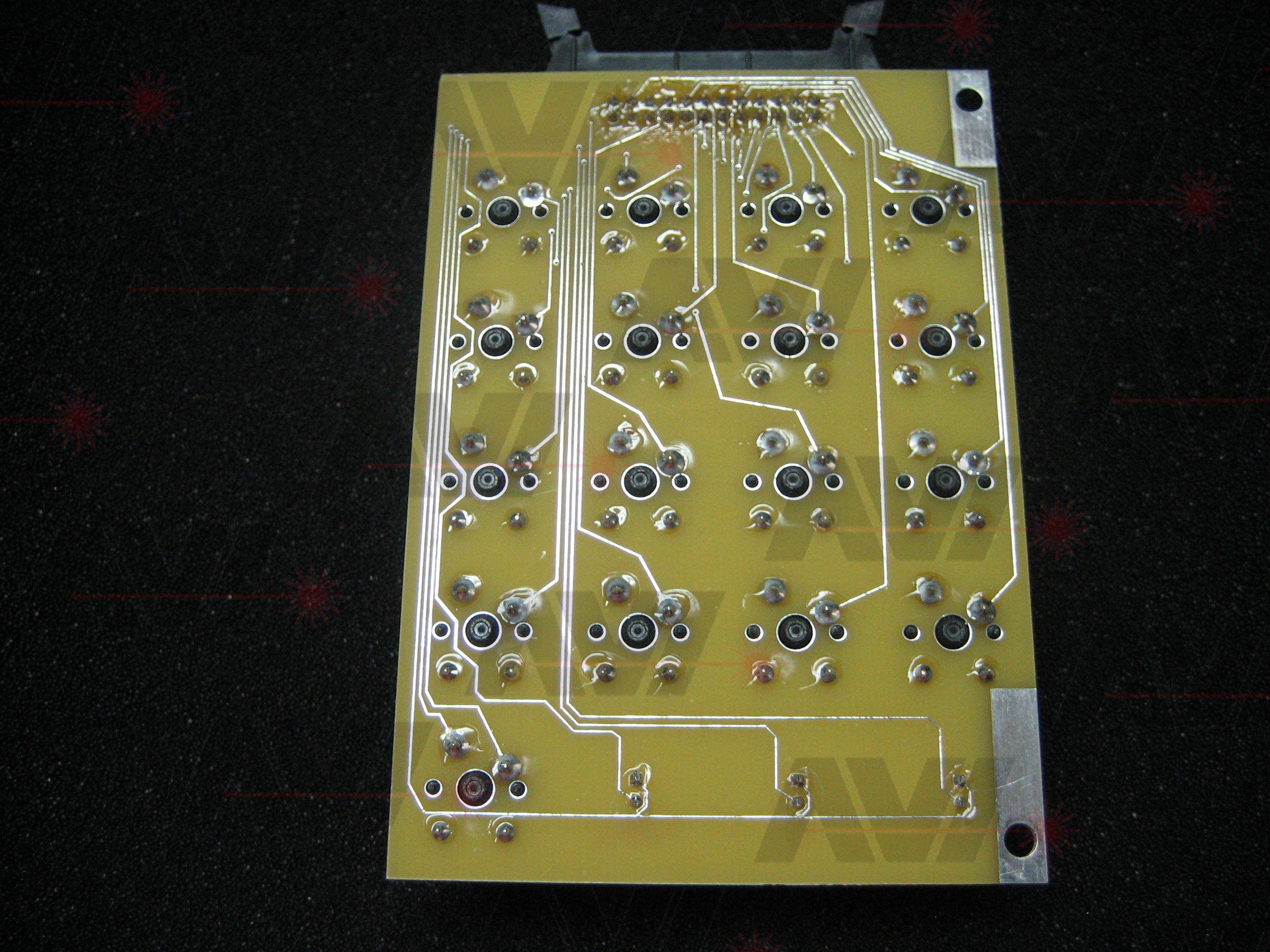
I had some trouble finding a reasonably priced 22/44 plug board. The Vector board was around $40, so I decided to just design a PCB and avoid point to point wiring the board.
Since I decided to have a PCB made I made a first attempt at an address decoder circuit based on the memory map in the FPB manual. I also added a footprint for an EPROM.
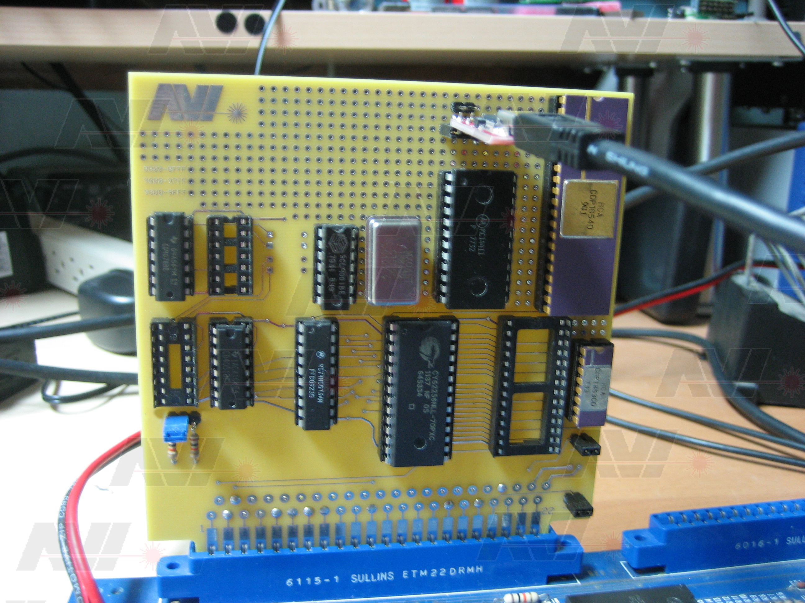
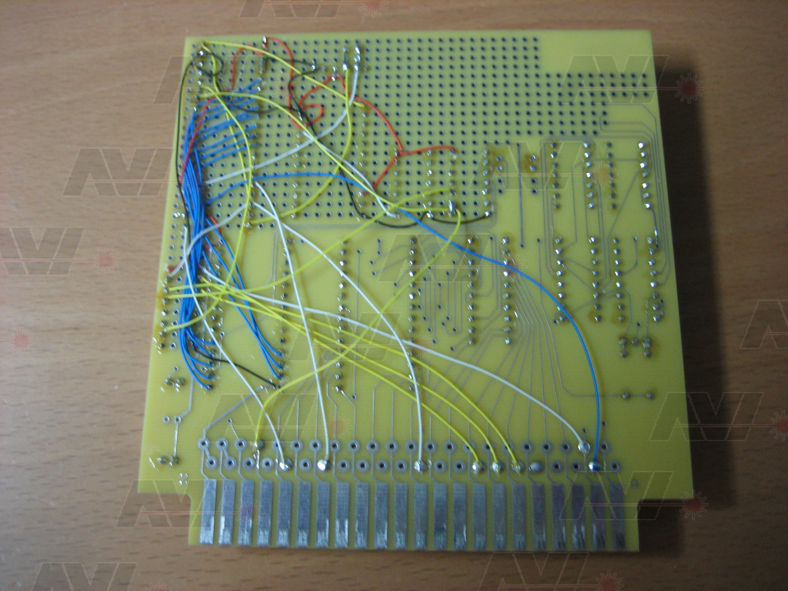
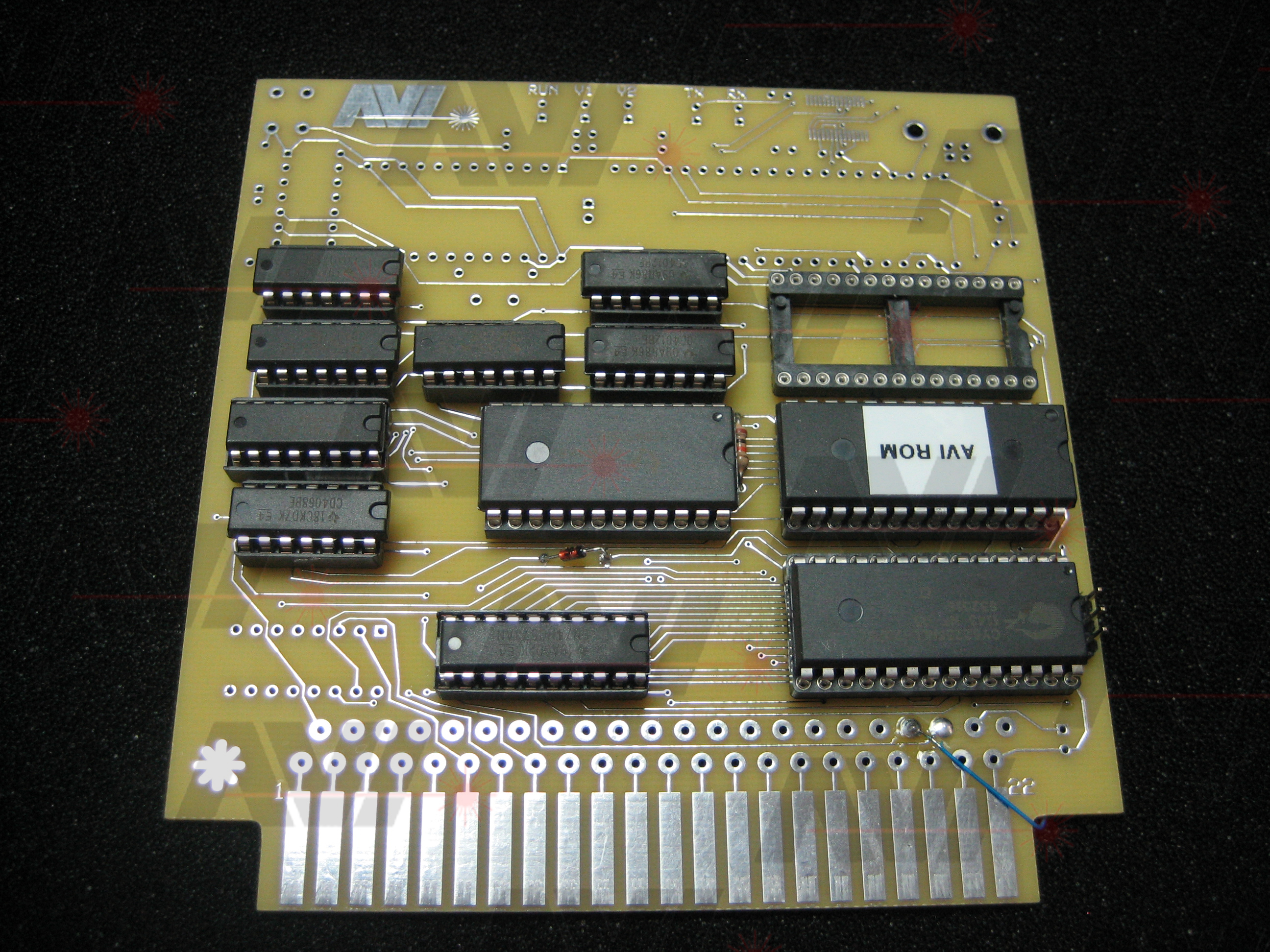
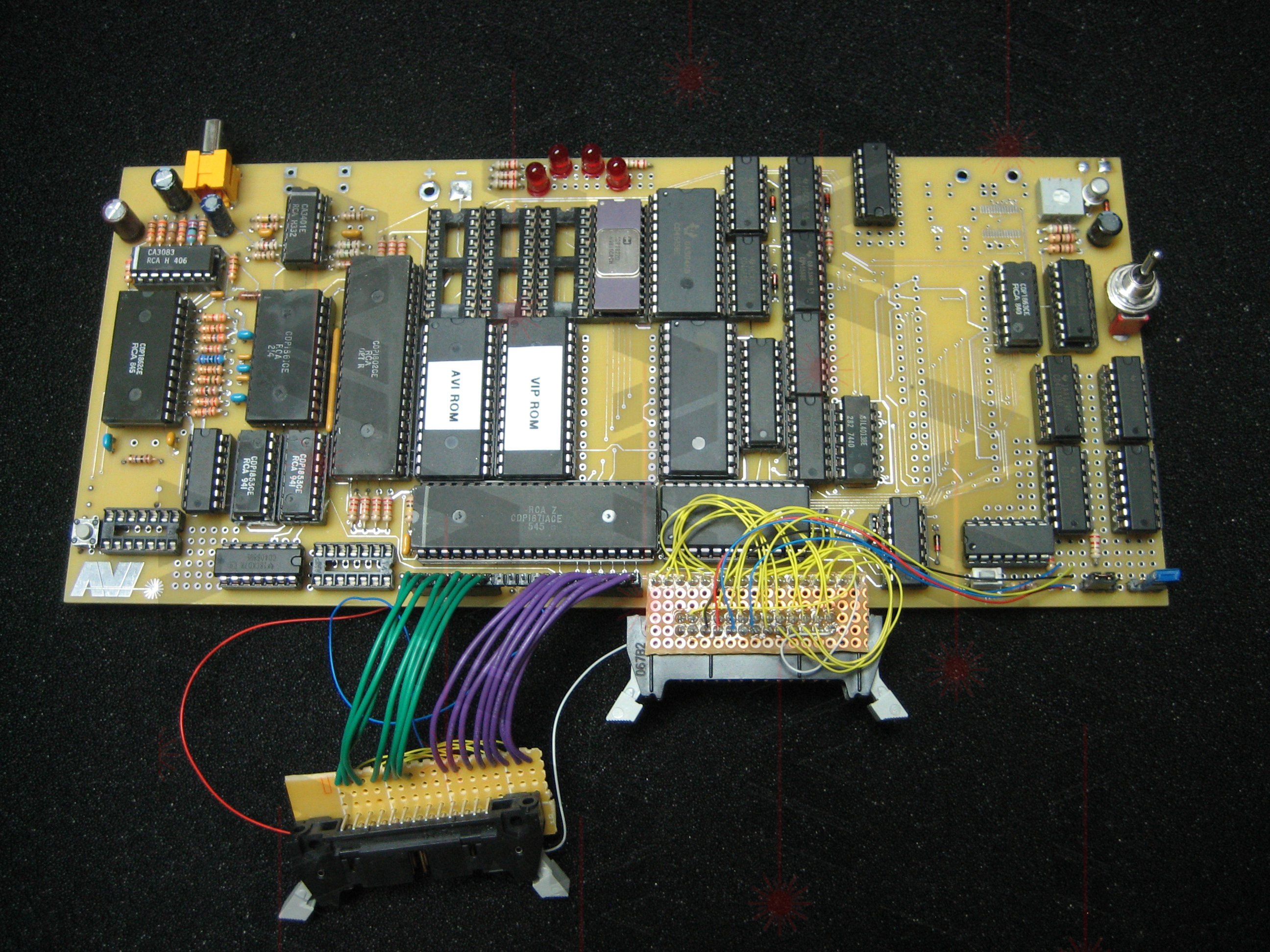
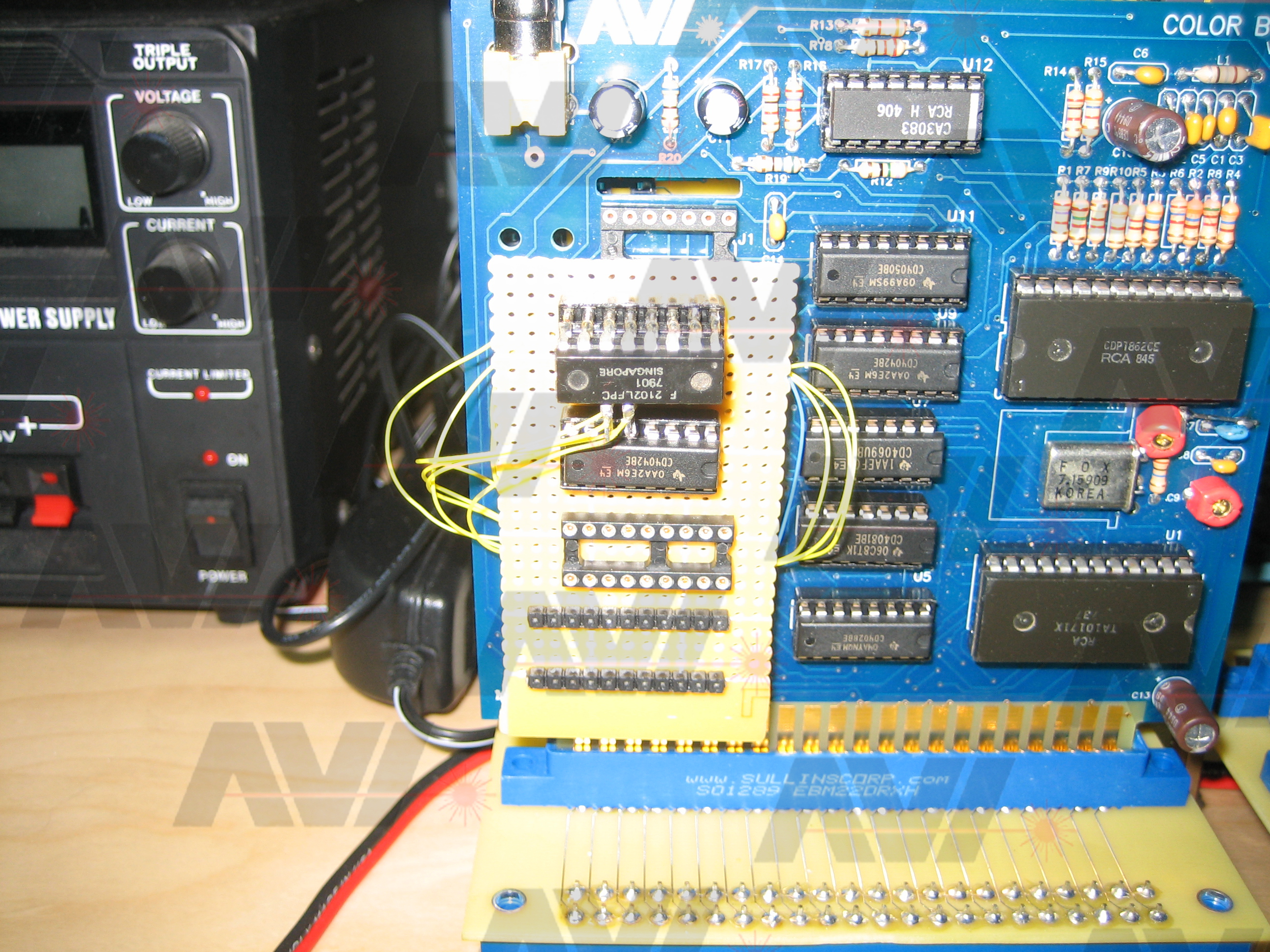
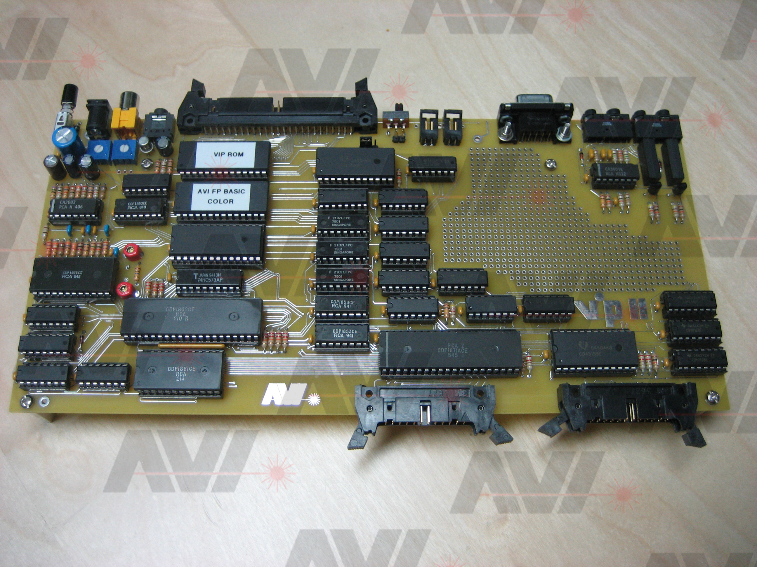
I ordered the PCB and installed the RAM and latch. I did some testing by writing and reading from the new memory. Everything seems to work. Here is a photo of it:
FLOATING POINT BASIC
I still have the cassette player I used way back when, but I bought a new one from Walmart. I didn't want to risk stretched belts and sticky rollers.
Using the original cassette I have, I tried to load Floating Point Basic. The manual has a section about how to use the bootloader, the first track on the tape. I was able to load that after a little fiddling with the volume of the cassette player. I saved it to a new tape just for safety.
Using the bootloader's read option, initiated by pressing the 'B' key on the VIP hex keypad, I tried to load the main program. No luck. It would load for about 40 seconds and then the 'Q' LED would flash. I really had to play with the volume control because the system was being really finicky. I was finally able to get it to load! Floating Point Basic takes about 4 1/2 minutes to read in.
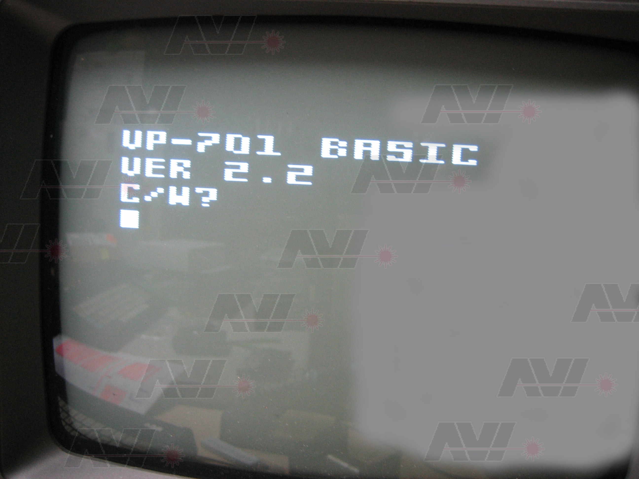
When I flipped the toggle switch on the VIP, I was presented with the version display and the 'C/W?' prompt. I didn't have a keyboard attached, so I reset the VIP and re-ran the bootloader. Using the 'F' option, I made a new copy of the main program. I popped the tabs out of the new cassette. I didn't take any pictures of that screen though.
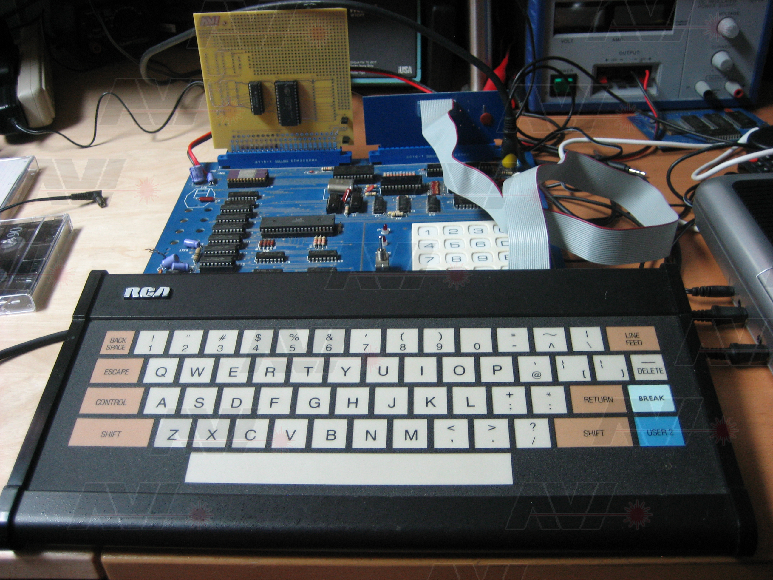
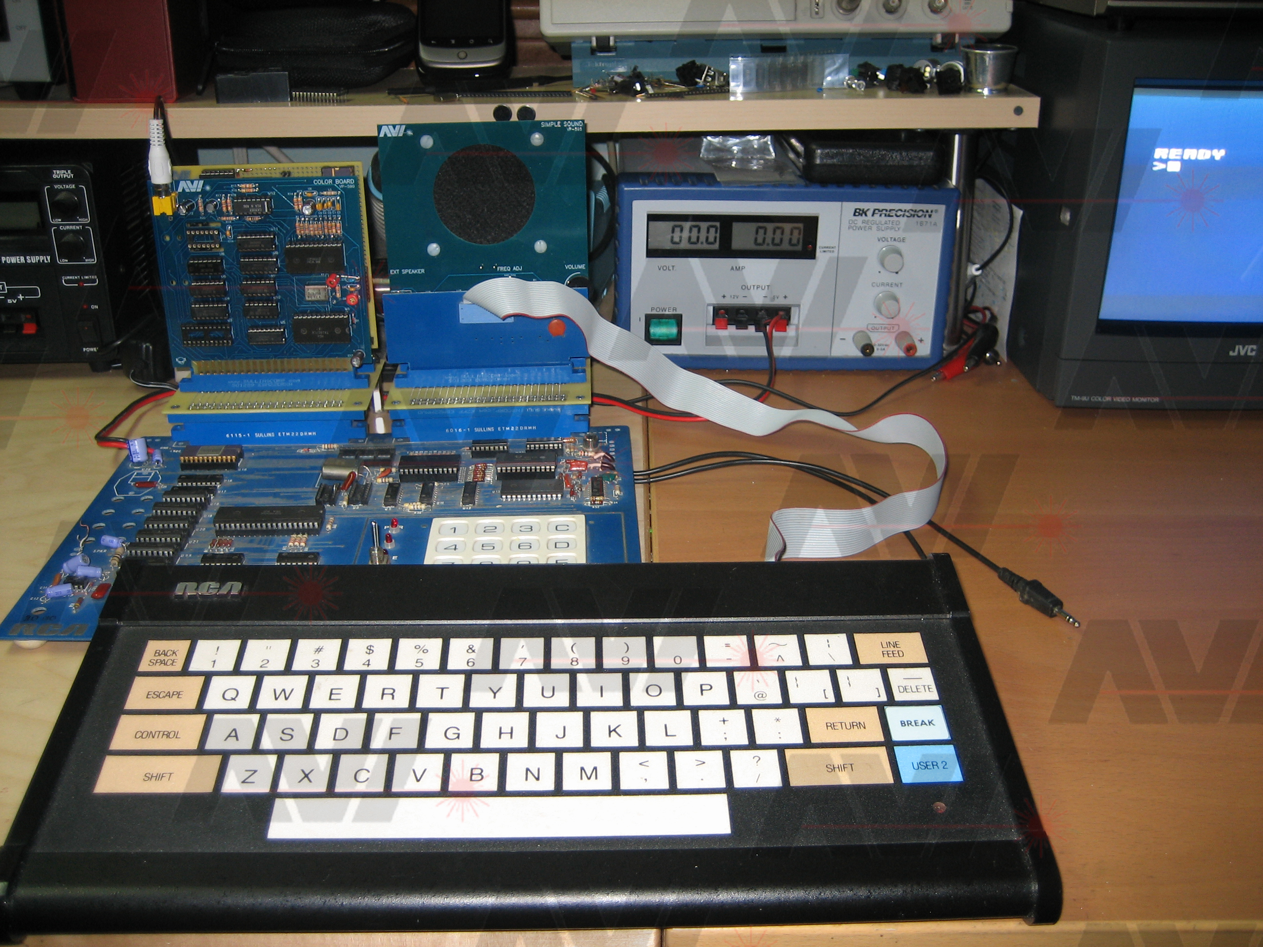
I dug out my RCA VP-601 keyboard and VP-620 keyboard interface. I had originally bought them so I could use Tiny Basic. I later used them for Floating Point Basic. I plugged the interface into the VIP's I/O interface.
BY Turning on the VIP and using my new cassette, I able to load Floating Point again. From now on I will refer to Floating Point Basic as 'FPB'.
When the prompt came up I pressed the 'C' key. The screen cleared and I was presented with a 'READY>' prompt. I flipped through the manual and tried out a bunch of the commands. Before I shut down, I typed numbers and returns to see how many lines FPB supported. It supports 11 lines. On the last line I typed the alphabet to fill a line to see how many characters per line FPB supported. Including the prompt, it supports 16.
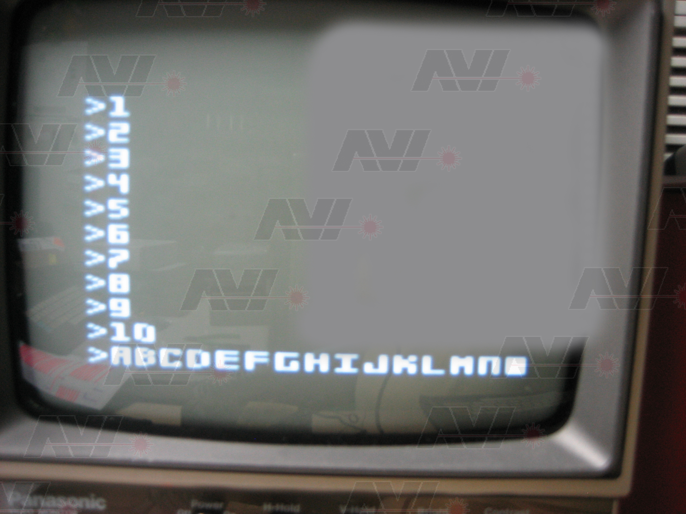
According to the VIP II brochure, it indicates that the VIP II supports 16 characters by 11 lines with line overflow and scrolling. FPB also does line overflow and scrolling.
PREVIOUS WORK
I read through the VIP II brochure again and it occurred to me that the VIP II was kind of an original VIP with a color board, simple sound board, ASCII keyboard, five board extender and a bunch of RAM cards.
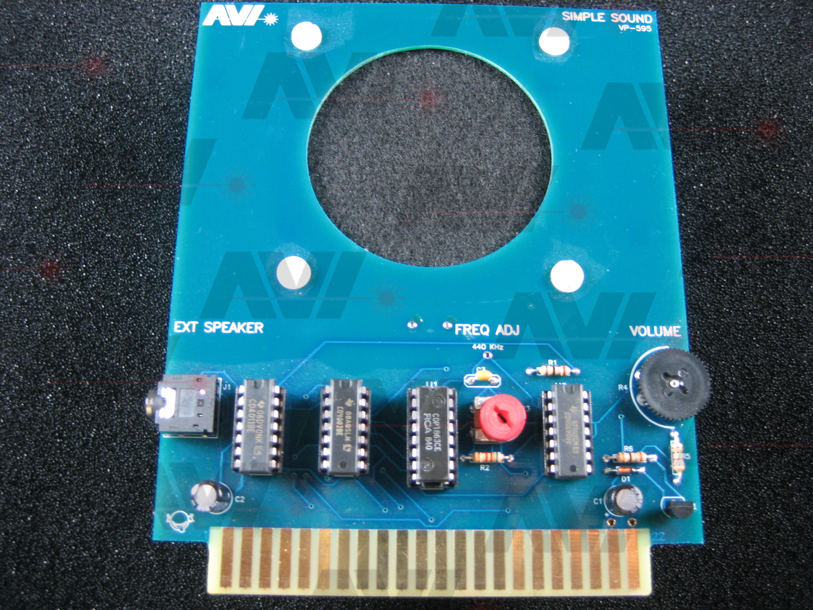
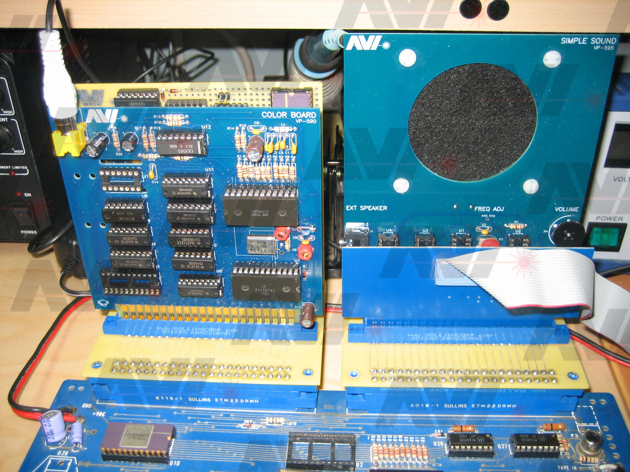
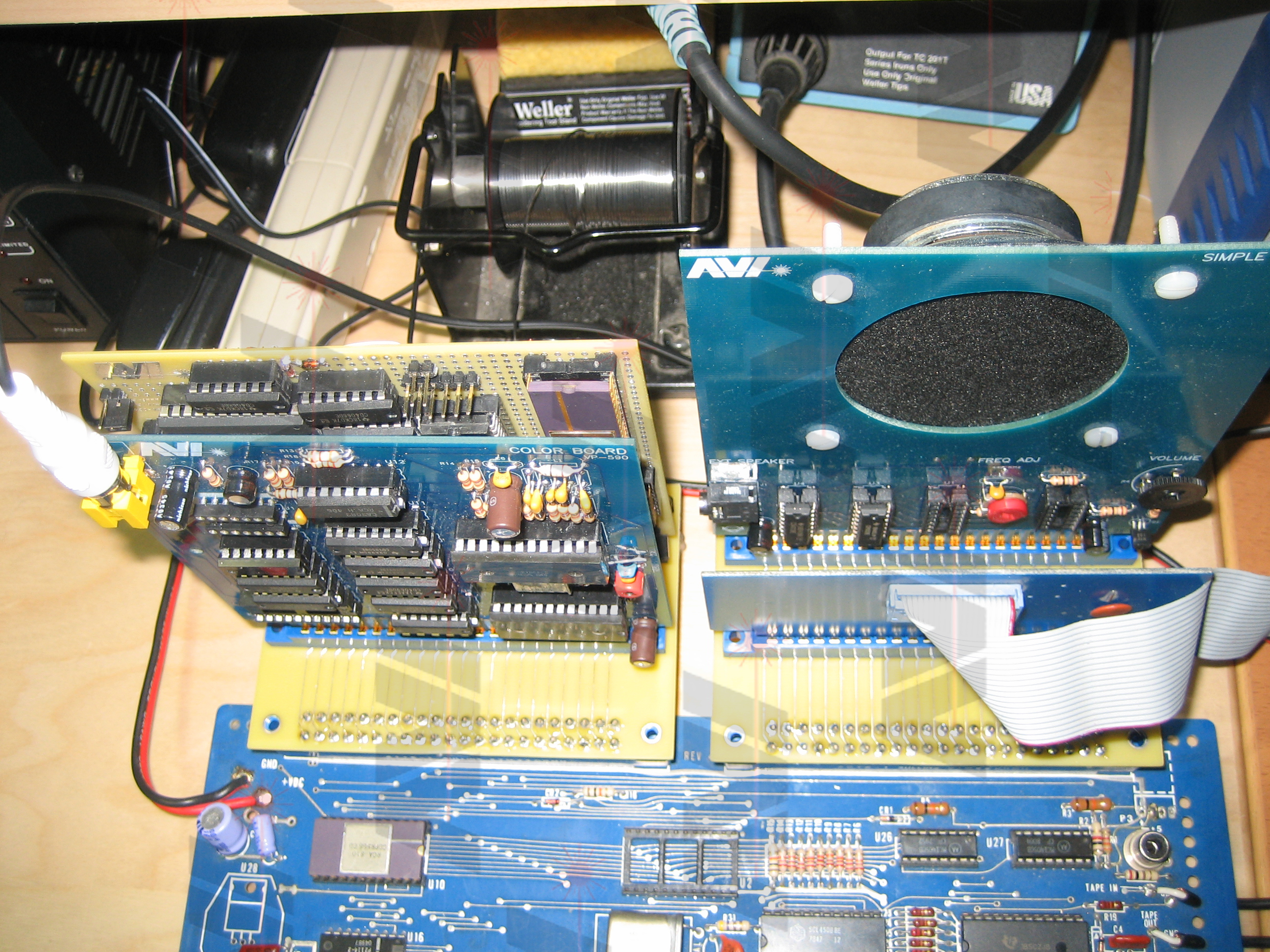
One of the boards I own is an original VP-595 Simple Sound board.

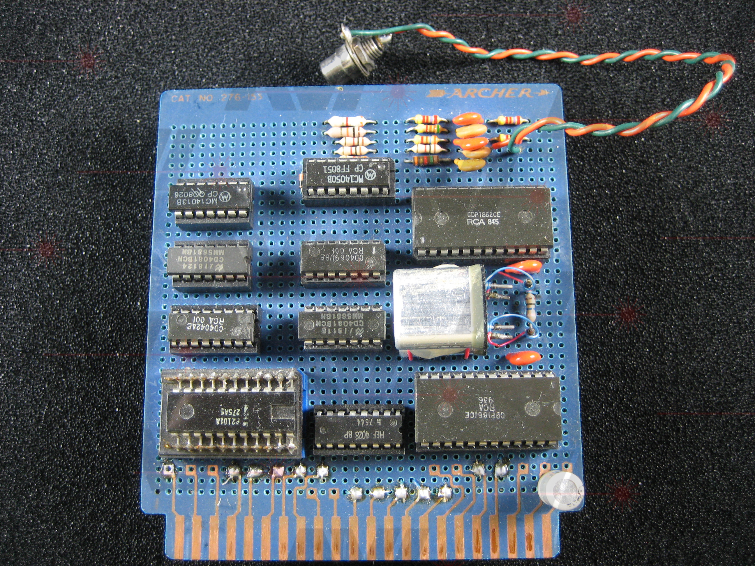
I had wire-wrapped my own color board when I was young.
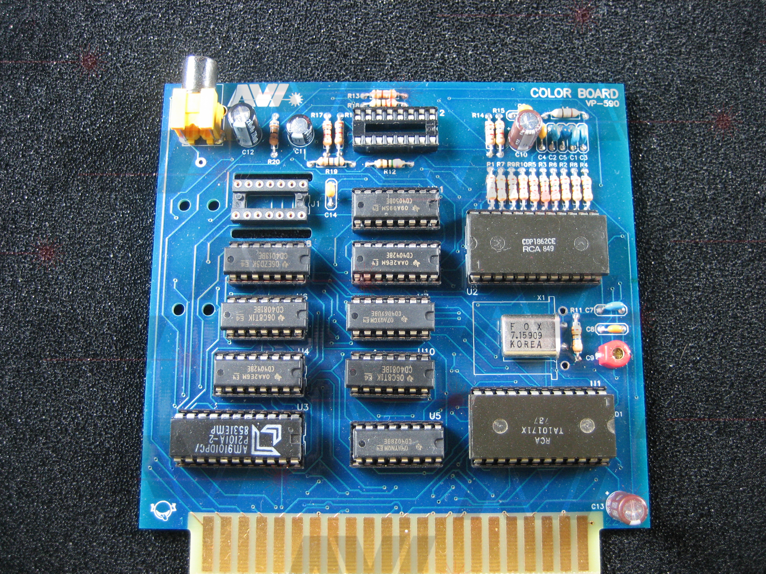
I had also recently recreated the color board and simple sound board as plug-in cards for the VIP.
RECREATING THE VIP II
Since I had already built those boards, I decided to try and recreate the VIP II.
Just to be safe, using the tape I had just made, I loaded FPB again and made another tape. I put this copy away for safe keeping.
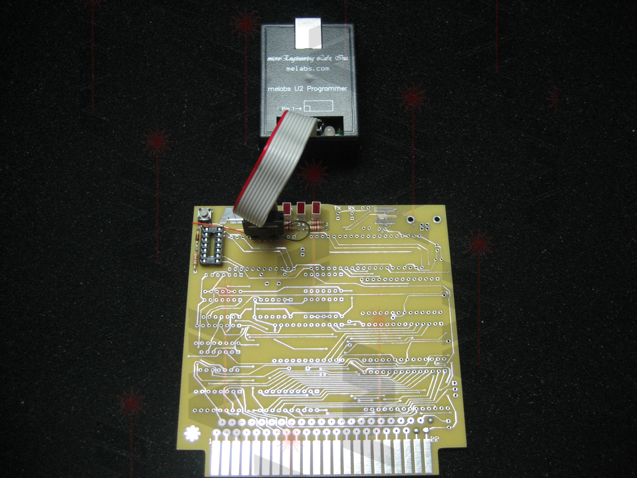
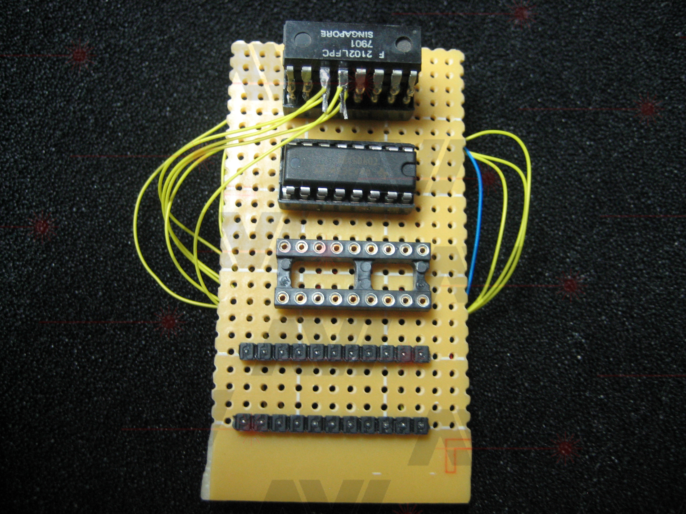
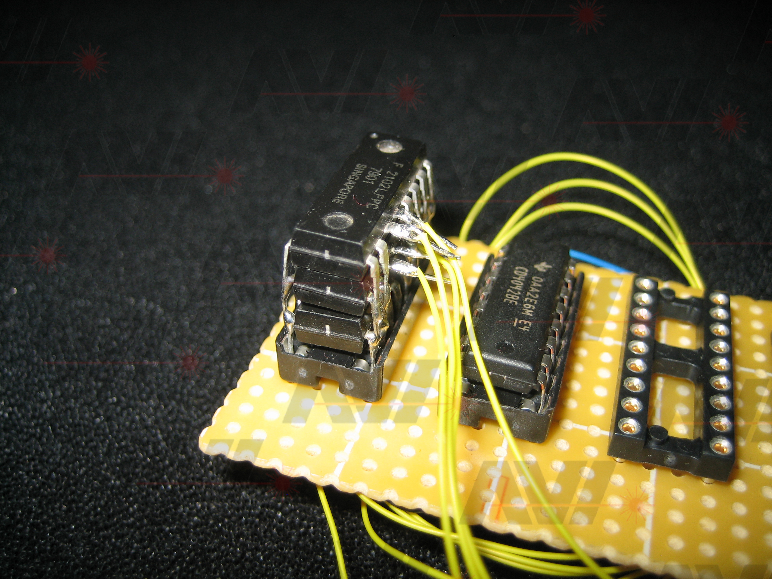
In order to build the VIP II, the first thing I would need to do was get FPB into an EPROM. I designed a UART circuit using the CDP1854 and an 1853 for N line decoding. It was designed for sending only, as my goal was to get the data into my PC so I could make the EPROM image.
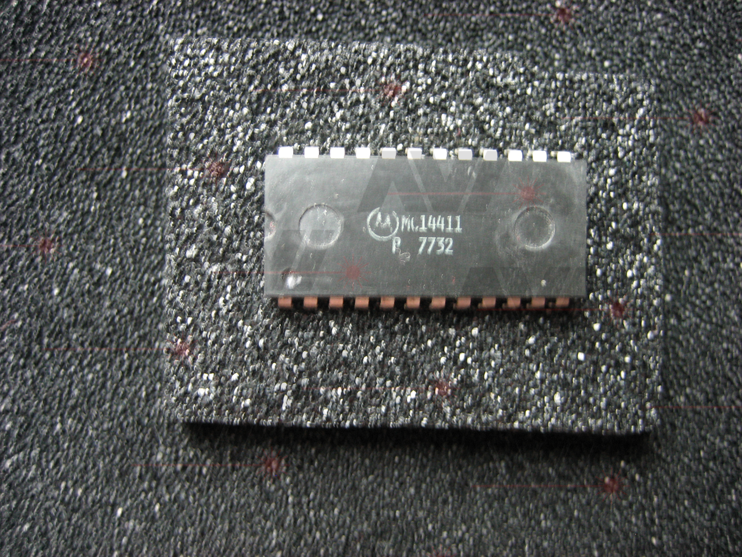
I needed a baud rate generator, so I bought a MC14411 baud rate generator chip off eBay.
I added a point to point wired UART circuit to the 32K RAM board.
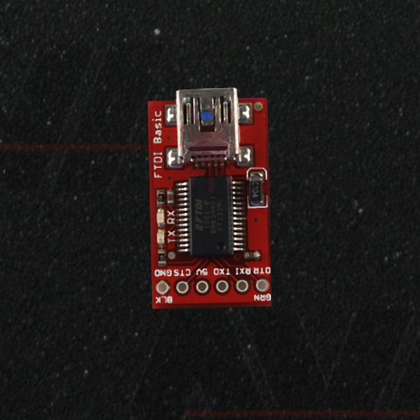
I used a simple serial to USB interface board to get the data to the PC.
I wrote a really simple program that dumped all 64K of 1802 memory space to the PC. I edited out the parts I didn't need. I verified the file dump was good by stepping through the VIP's memory. After quite a while, I was sure the dump was good.
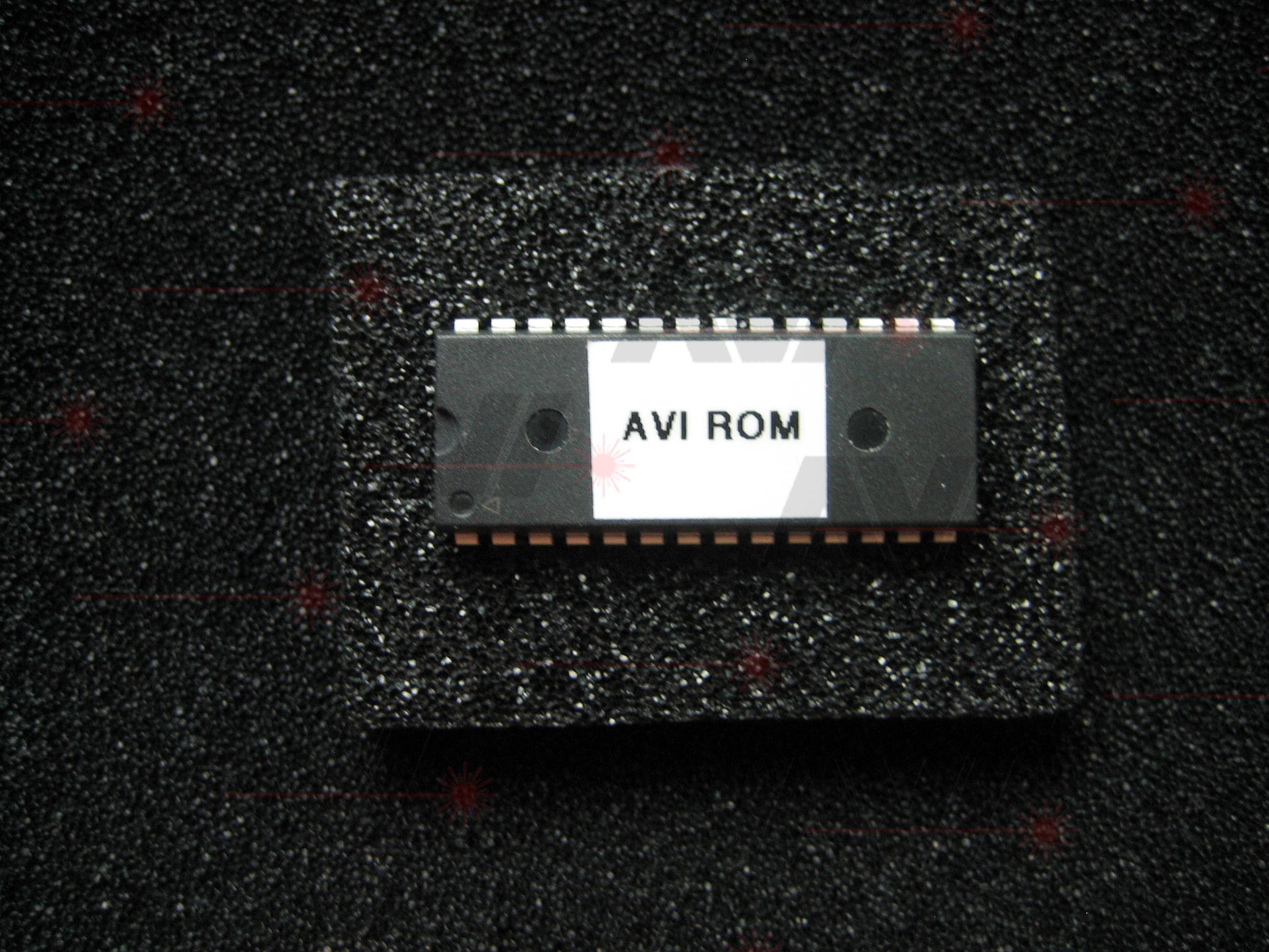
I converted the raw hex data into an INTEL format hex file and loaded it into an ATMEL AT28C256 EEPROM.
BOOTING FROM ROM
I was excited to see FPB load from my new EEPROM, so I added a new socket to the RAM board in the EPROM location and built up the address decoder section. Nothing.
The first address decoder I had thrown together when making the PCB was a failure.
I studied the memory mapping for FPB and designed a new address decoder.
FPB needs the bootloader to run. When loaded, if you reset the VIP and run it again, it just sits there. The bootloader is waiting for a command. By pressing '1' on the VIP keyboard, the bootloader jumps to and starts running FPB.
The bootloader would also need to be in the EEPROM. So the memory map needs to look like this:
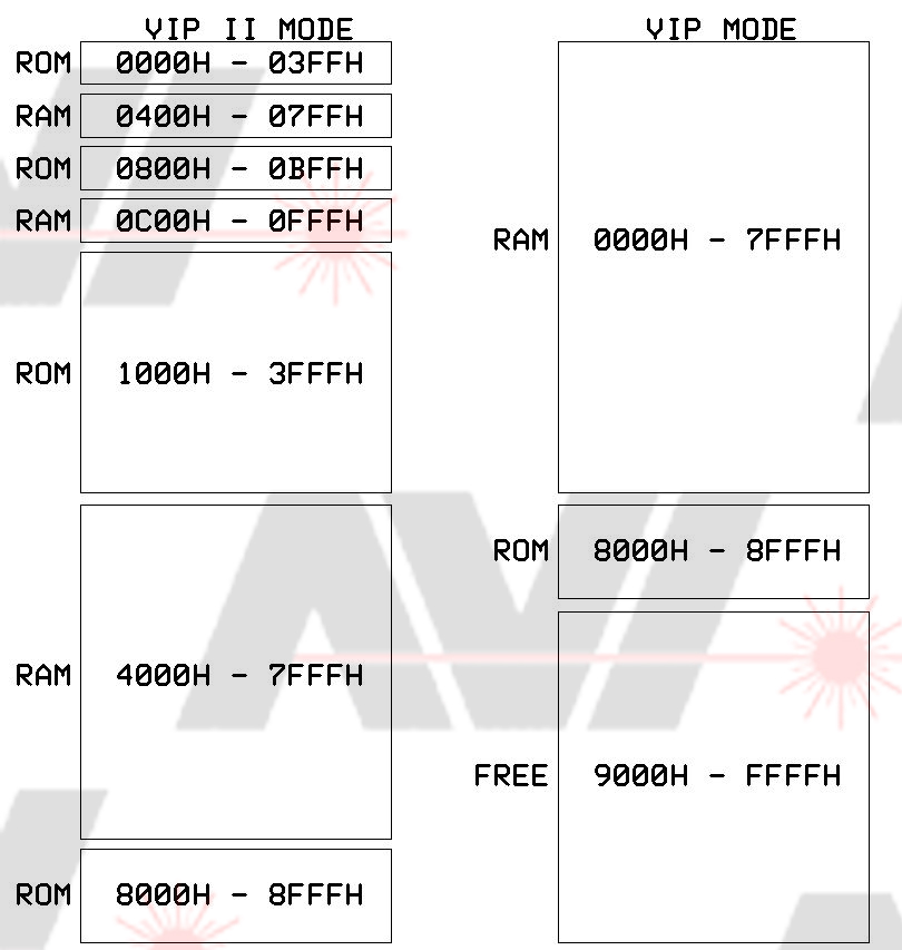
RAM and EEPROM kind of need to be mingled together. Since I wanted to keep the chip count down for the VIP II, I designed the address decoder to handle this.
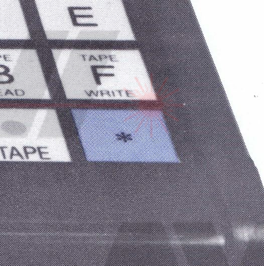
THE STAR BUTTON
I'd been thinking about the key just below the hex keypad on the VIP II. It is a small blue key with an '*' on it.
The brochure doesn't mention what it was to be used for, but it does mention that the VIP II can be used as an original VIP with CHIP-8 and Machine Language.
I think the 'STAR' button would be used as a 'RUN' switch. The original VIP requires a RUN/RES switch. The VIP II also requires a run switch to exit a hung FPB program. On the VIP while running FPB, flip the switch to RES and then to RUN. When FPB come up, choose warm start and the basic program stays intact.
The brochure also doesn't mention how one switches between VIP II and VIP I mode.
ADDRESS DECODER FAIL
I had a new address decoder PCB made that also added the UART circuit and a USB interface. I assembled and tested the decoder section. It did not work. I made a critical mistake while I was laying them out and didn't catch it. I will use them for future prototype work.
WORKING ADDRESS DECODER
I designed a new address decoder. I built the circuit on the 32K RAM board in the last of the available space. I got it to work. Set the VIP to run, press '1' and FPB comes up. I needed to work out a couple of small issues but got the address decoder to work.
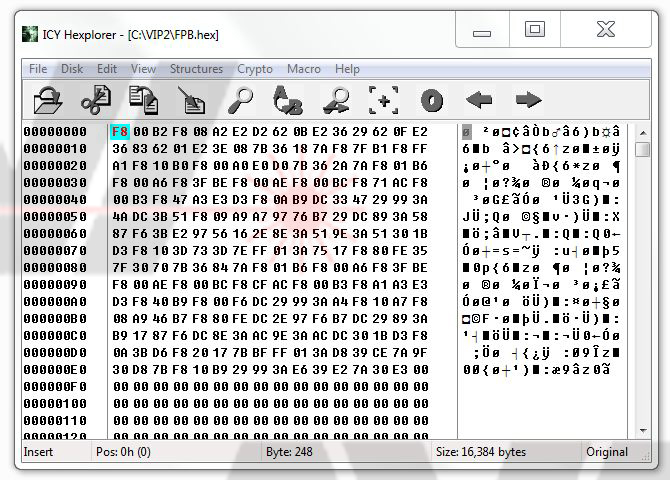
I loaded the bootloader into a hex editor (I use Hexplorer) and looked through the code. I found and modified the bootloader so pressing '1' to enter FPB was no longer needed. Flip run and you're in FPB at the 'C/W?' prompt.
I preserved the ability to use the 'B' and 'F' tape options of the bootloader. The 'B' option runs but has no effect, obviously, because of the EEPROM being in address space needed by FPB. It would normally be RAM on a VIP system.
The 'F' option runs fine leaving the ability to dump FPB as needed.
SOUND
The next thing I tested was sound. I used the simple sound board I built.
Since the VIP only has one byte I/O port, and FPB uses it for the keyboard interface, I typed in a small test program and typed 'RUN'. I then pulled the keyboard interface and inserted my simple sound board. The sound worked as described in the FPB manual.
I redesigned the simple sound board circuit to reduce the number of chips on it and remove the need for an I/O latch. The VIP uses two CD4508s for latching input and output.
The simple sound board contains circuitry for the special case of 00h on the latch. When 00h is on the latch no sound is produced. A CD4002 and a CD4011 were added to the simple sound board to force a 80h into the CDP1863 chip when the latch is set to 00h. When the VIP boots up, the ROM clears the latches on the byte I/O. This way the VIP will make a tone when a keypad button is pressed.
The datasheet for the CDP1863 indicates that it is internally set to a fixed divide rate when it is reset. This creates a tone that is a little higher than the 80h tone of the original Simple Sound card, but still works as a keypress tone.
KEYBOARD CIRCUIT DESIGN
I was thinking about having a custom membrane keyboard made, but membrane keyboards are too expensive!
Started looking into keyboard encoders and found most have a current key layout.
While looking at the VIP II brochure, I noticed the key mapping is really close to the CDP1871 from RCA. The main difference I saw is that the 'delete/underscore' key is backward and there is no way to directly add a backspace key.
I designed a circuit using the CDP1871, really not much to it. I point to point wired it on an unused PCB. I added 5 buttons for testing. The keys are 'C', 'A', 'V', 'I' and 'CR' - C to do a cold boot, AVI just for some keys and CR to enter them. Pressing the 'CR' button after 'AVI' causes an error, as expected. With the addition of a full complement of buttons, the keyboard should be okay.
MORE SOUND TESTING
Using the same board that I built the test keyboard on, I built my modified simple sound design. I did not build an amplifier.
I was able to remove the oscillator formed by the CD4069 on the original simple sound board. I used TPB as suggested in the CDP1863 datasheet. Removing the CD4002 and CD4069 and just relying on the reset divide rate provided a tone a little higher that the unmodified simple sound board.
TESTING COLOR VIDEO
I needed to test FPB with the color board. Since the VIP only has 1 expansion and 1 byte I/O port, I built a couple extender boards.
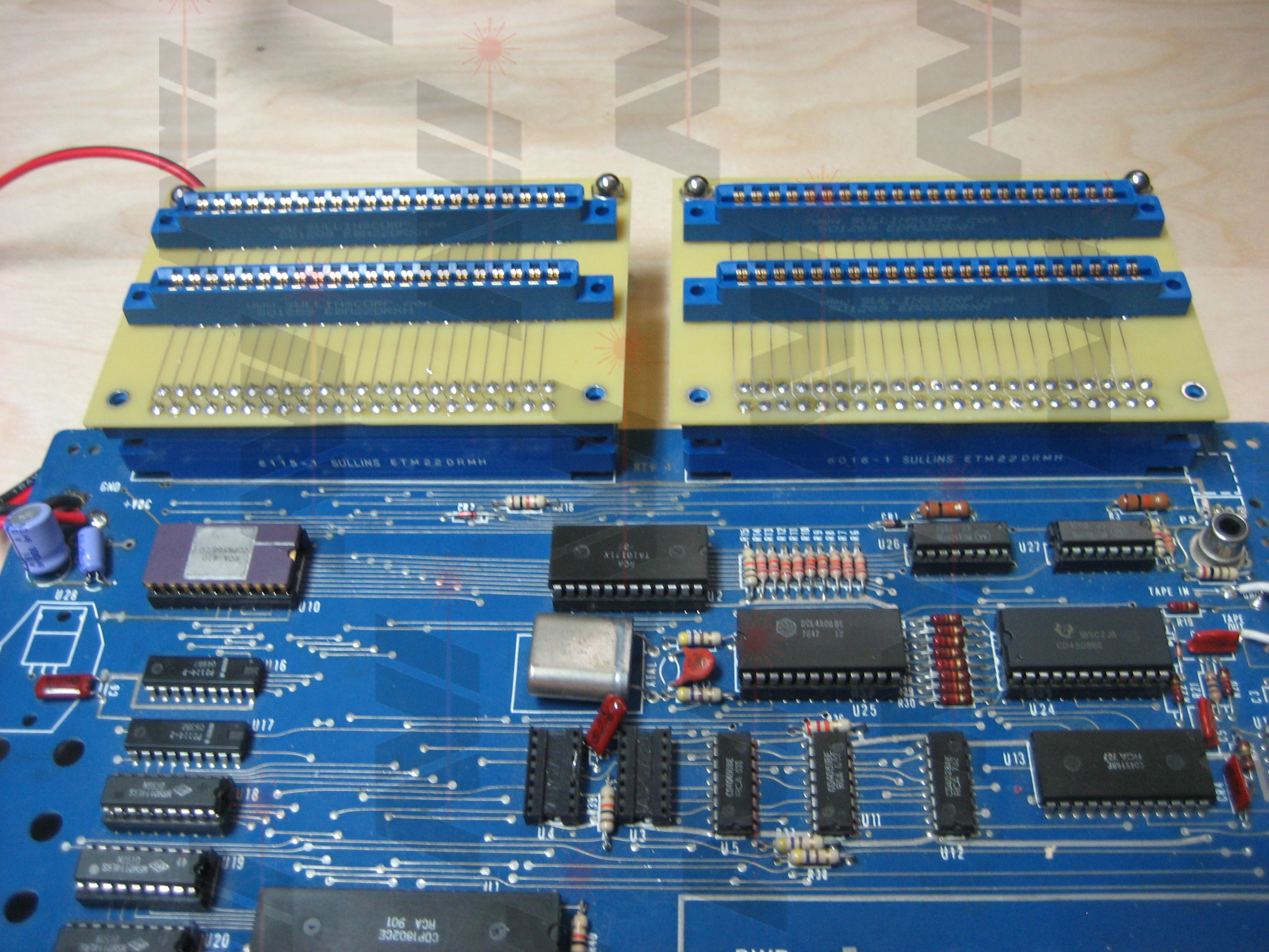
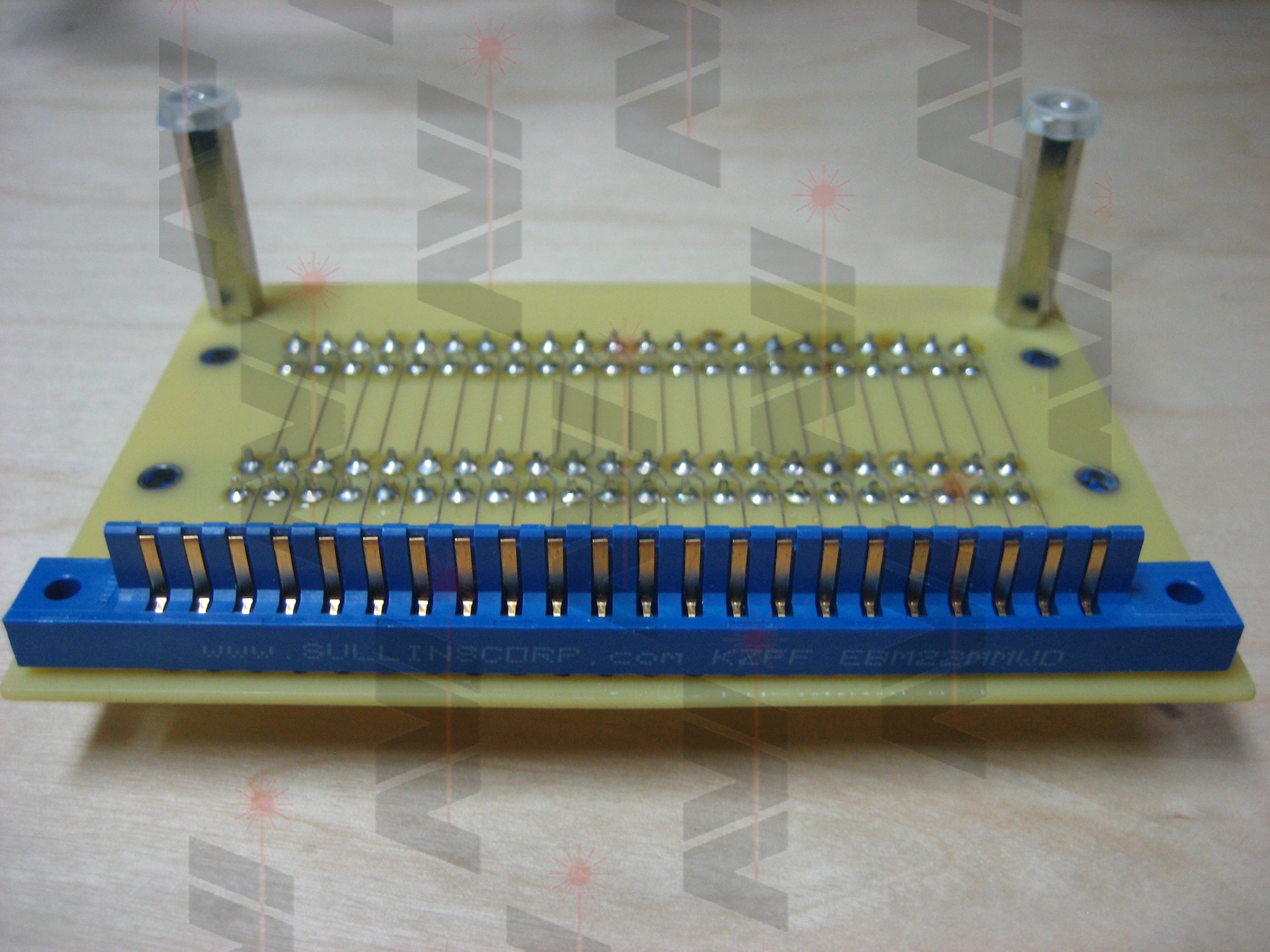
Now I can test with the 32K/EEPROM/Address Decoder board and the color board installed in the expansion port of the VIP. I also can have both the keyboard interface and the simple sound board installed in the byte I/O port. In these photos, the video RAM is not installed on the color board.
Using the extender board, I was able to plug in both my FPB board and color board. I started testing.
FPB is shipped with color support off, in case the user did not have a color board. As described in the FPB manual, I modified the locations that are required to use the color statements built into FPB. I burned a new EEPROM.
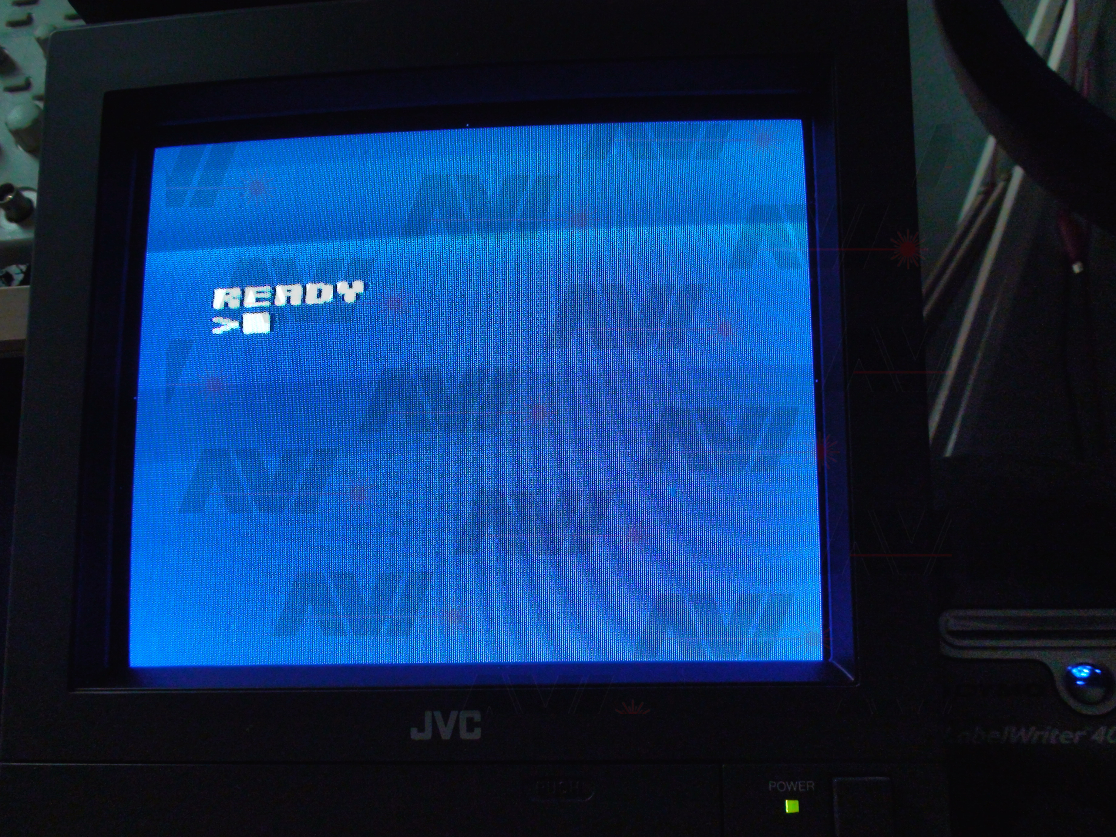
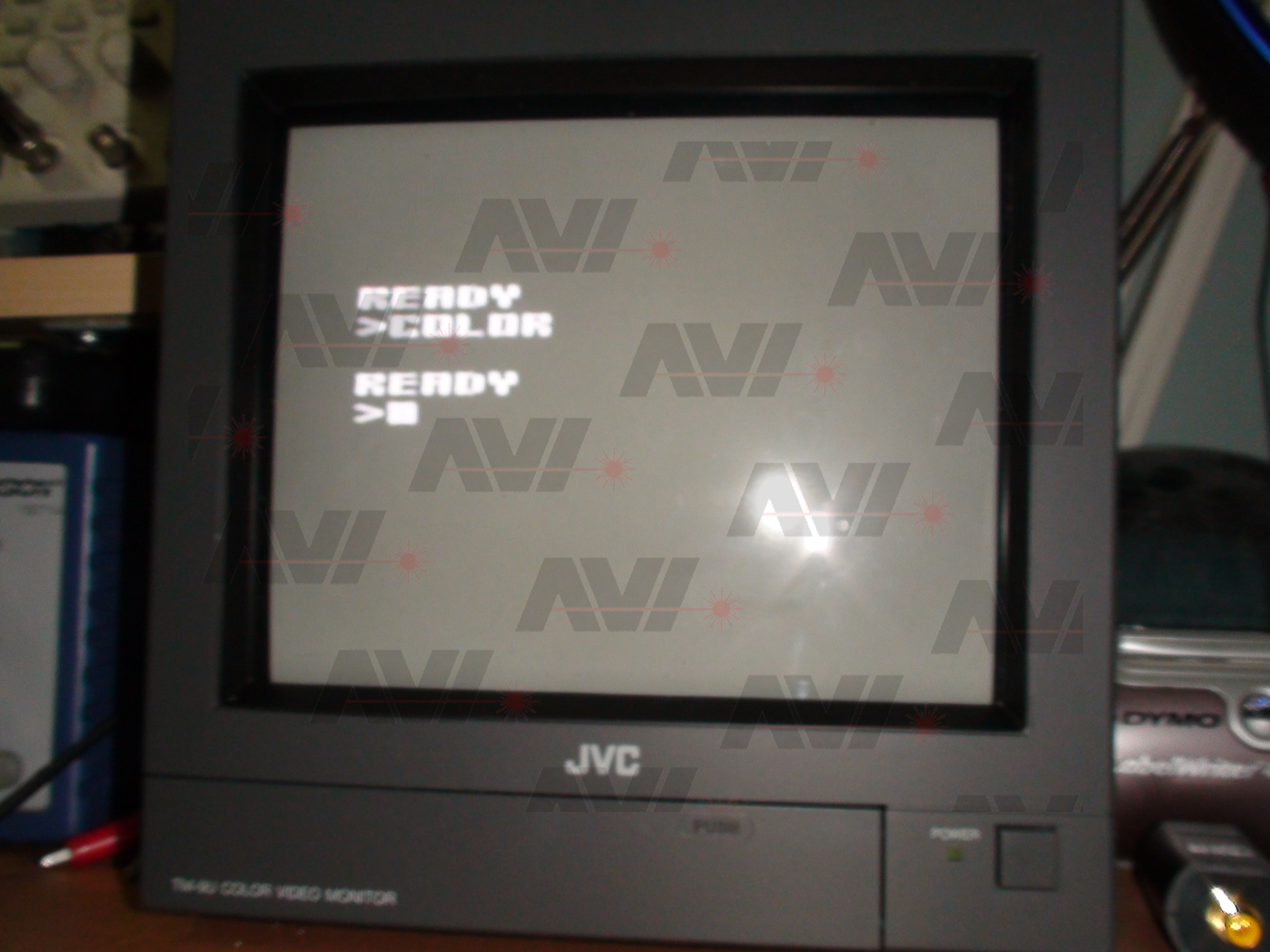
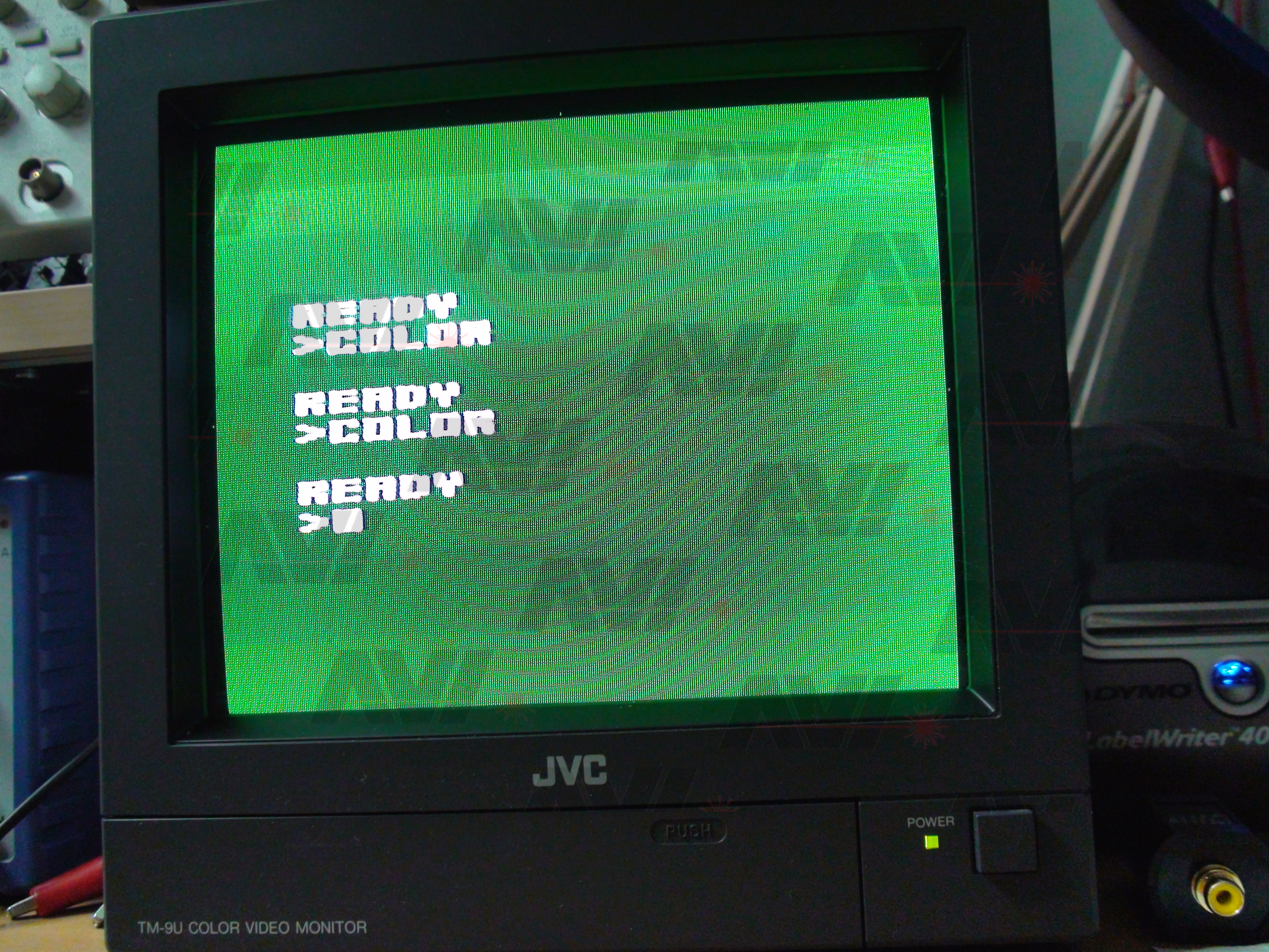
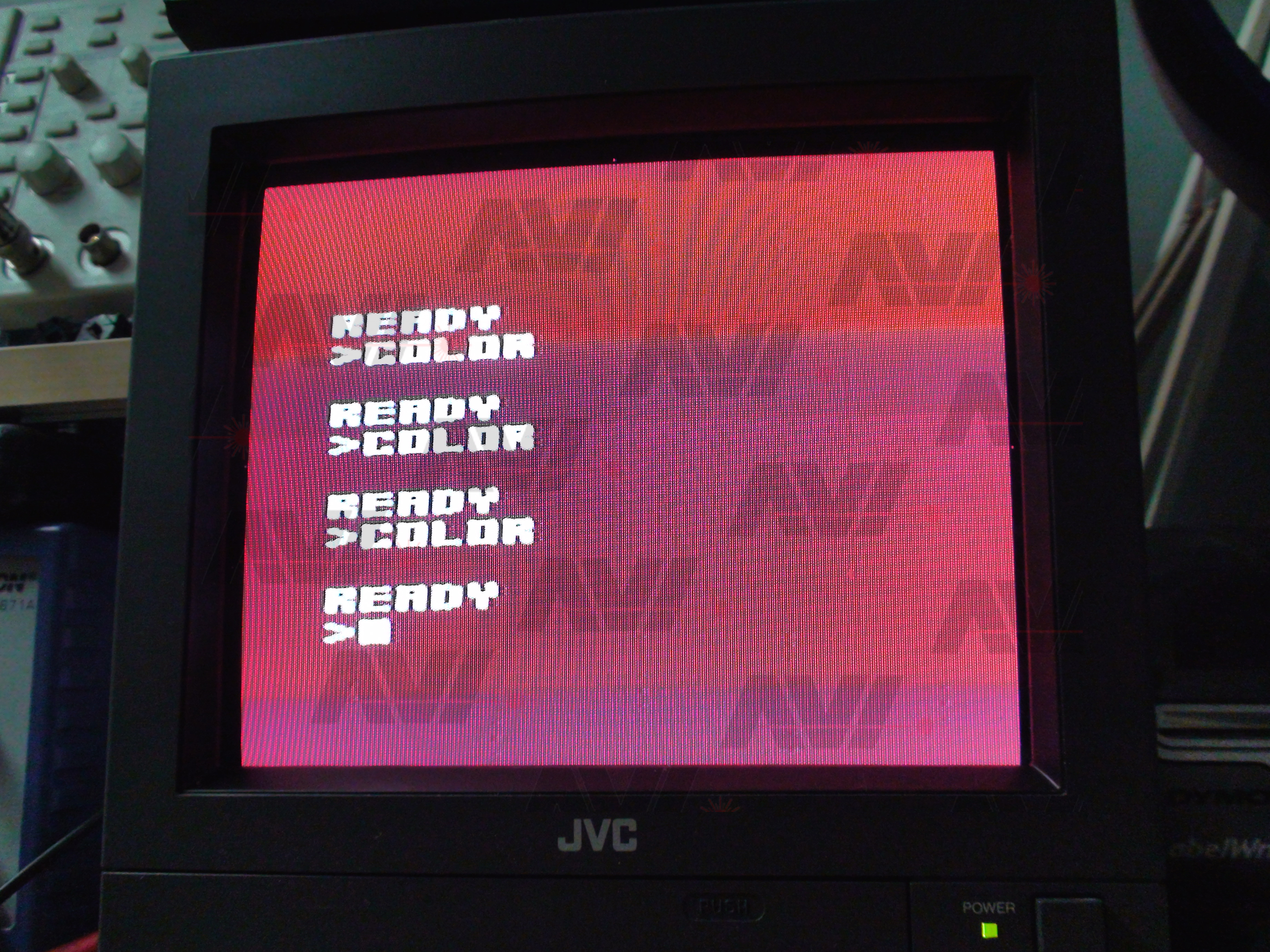
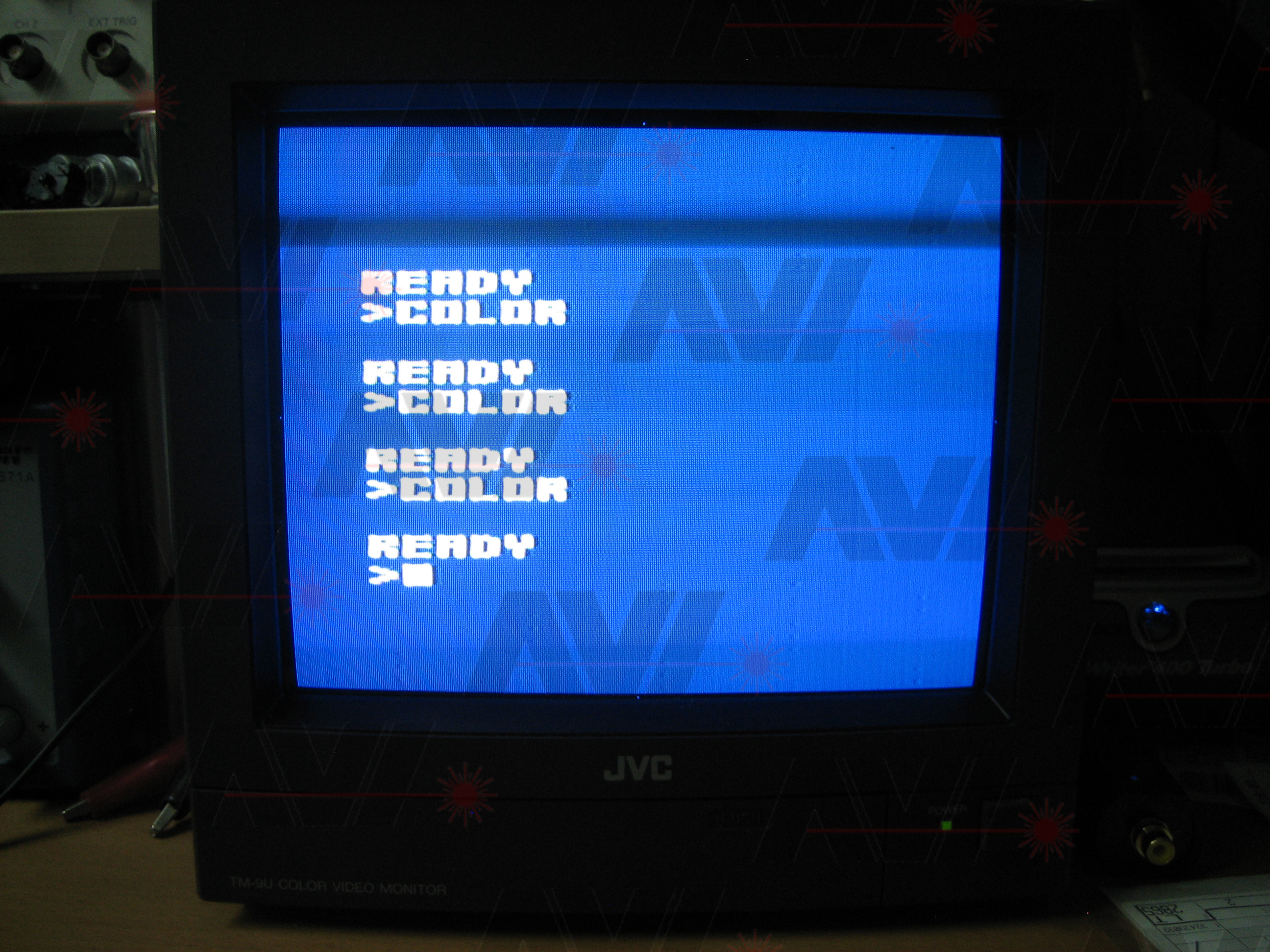
I booted up FPB normally. At the 'READY>' prompt (WHITE text on a BLUE background), I typed in 'COLOR' and hit return. The background color changed to BLACK, as it should. I cycled through GREEN, RED and back to BLUE. The black bar and interference in the images is due to the camera, and not in the actual image.
MIRRORED COLOR
After messing around with the 'COLOR' command for I while, I typed 'COLOR (1,0,0,8,128)' and the foreground changed to RED. As described in the manual, I saw the 'mirroring' effect it described. This is caused by the color board only having 256 bytes of RAM. The VIP II brochure indicates that the VIP II has '1024 color zones'. The CDP1862 datasheet indicates that to have '1024 color blocks', 1k by 3 bytes of ram are needed. Separate IN and OUT Data pins are also required on the RAM. I may need to modify FPB to allow for 1K of memory.
I opened the FPB hex image in hexplorer. Using the FPB manual's color board modification locations as I guide, I looked through the code. In the 'CLC' command, I noticed 'F8 D3 BF F8 FF AF', this would set the top of a 1K buffer that starts at D000h. The code following does a memory fill, clearing the color table. It looks like FPB is written with 1K of color memory in mind.
The color board uses a CDP1822 ram chip that is 256 x 4 bytes, with separate I/O. Since I have some CDP1822s, I decided to design a circuit using 3 of them.
NEW CIRCUIT BOARD
I decided to combine all of the smaller projects I have done into one schematic, reducing the chip count along the way.
After rereading the VIP II brochure, I gave some thought as to how I could make the VIP II also act as a regular, original VIP.
The first thing that would have to happen would be 2 different memory maps. The VIP II bootloader is located in ROM at 0000h. The VIP has a special circuit to force the monitor ROM to address 0000h for the first few bytes then jump to 8000h. The VIP also uses a simple address decoder for the ROM that makes use of all memory addresses above 8000h. This makes adding memory in that area a hassle without modifying the VIP.
I made a decision to modify the address decoder circuit one more time to allow FPB to run as expected and also decode memory into 4K blocks. This would allow me to segment the memory for VIP II operations and in addition make the VIP ROM only take up 4K of space, instead of 32K. The VIP ROM is only 512 bytes long, but I thought I may extend it one day.
At this point I decided to make a new PCB that combined everything designed so far. The result is this:
BUILDING THE NEW BOARD
I built the board one section at a time to simplify debugging. First I got it working in VIP II mode. It is only booting up at this point with no color, keyboard or sound.
When I built the CDP1861 section, I added 3 external resistors to combine the video and sync like the VIP so I could test the video without the color circuit. BLACK and WHITE video works.
I then built the keyboard encoder section and added only one button, 'C', just to make sure it was working. Using a loose wire soldered to one of the sense lines, I tested other 'keys' of the CDP1871.
I added the color and video amplifier sections. I did not add the color memory yet, just left the 3 color data pins floating and held the 'Color On' pin, CON - pin 3 of the 1862, at +5. This sets the 1862 to WHITE on BLUE. Video works fine in color, so far.
I removed +5 from the CON pin, the CDP1862 went into color mode and the screen began flickering. Since there was no color memory I figured it was okay. I added the 1822 ram chips. The video stopped flickering, but the screen would not allow color changes.
I looked into the address decoder, and in my haste I didn't take into account the special mapping the color board uses, C000h-C0E7h for low resolution and D000h-D3FFh for high resolution. The address mapping for the color section was just wrong. I stopped testing the color section.
I modified the address decoder to allow this board to operate as a normal VIP or a VIP II with a single selector.
The circuit I designed to handle the special boot sequence of the VIP (starting at 0000h and jumping to 8000h) is holding the address decoder in inhibit all the time and broke VIP II mode.
I added circuitry to fix the boot problem, in the prototyping areas I put on the PCB . I also had to add a CD4068 to indicate when the RAM was active in VIP mode.
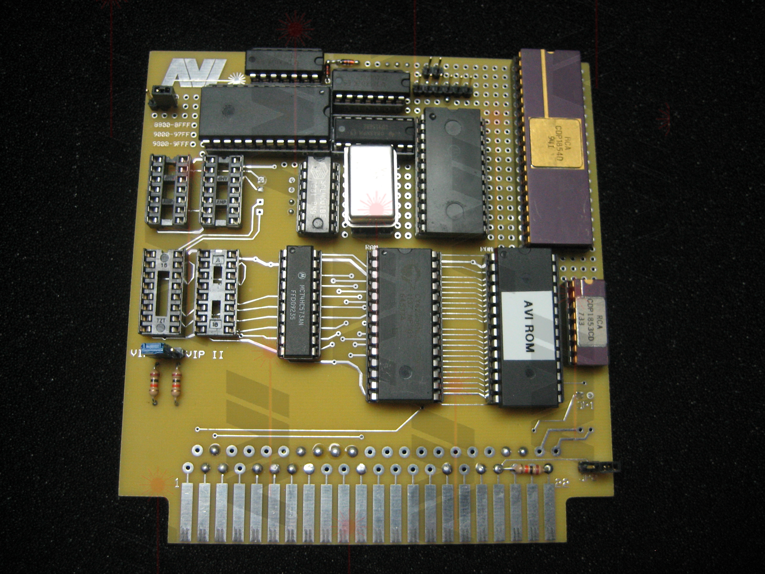
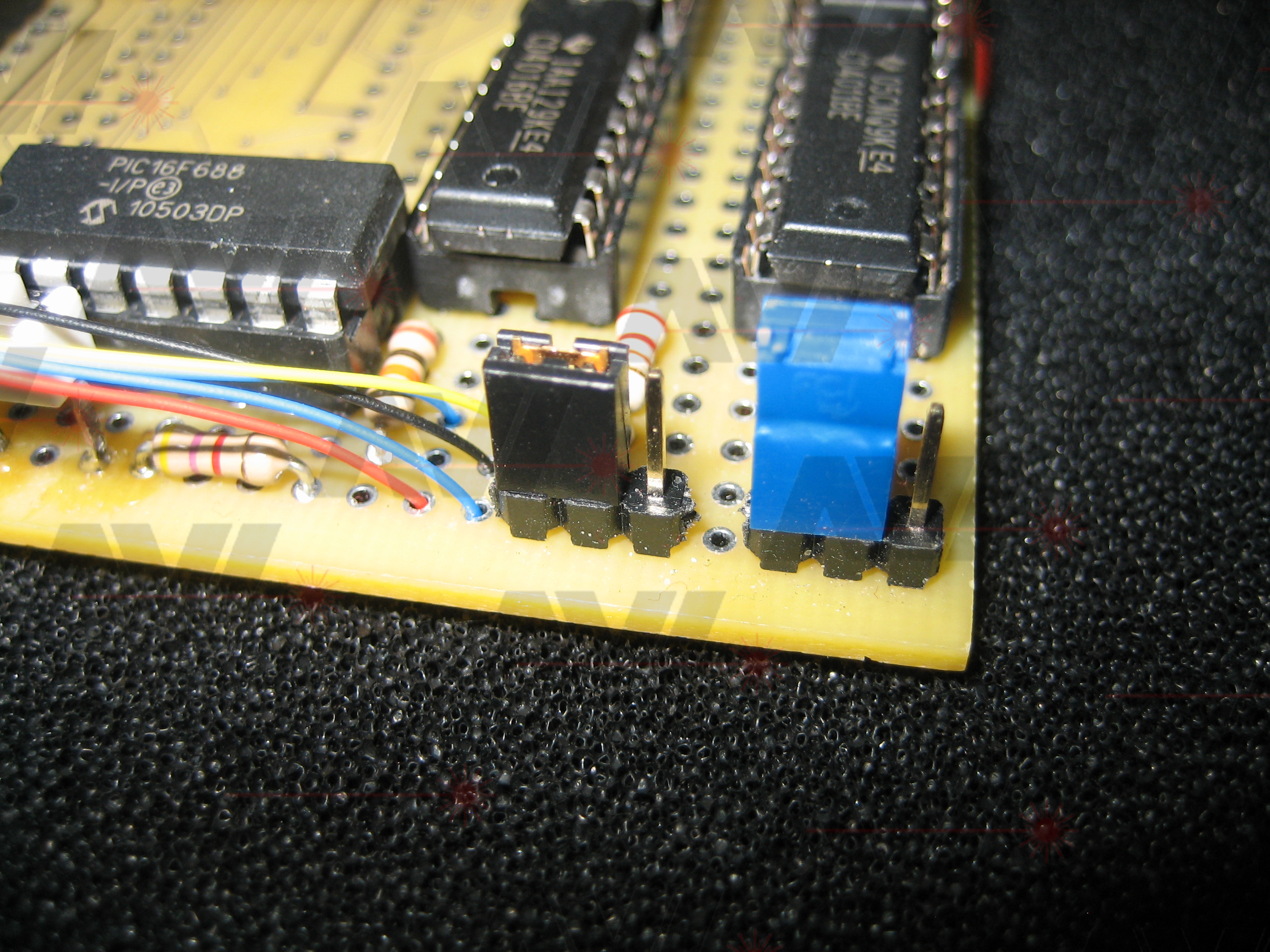
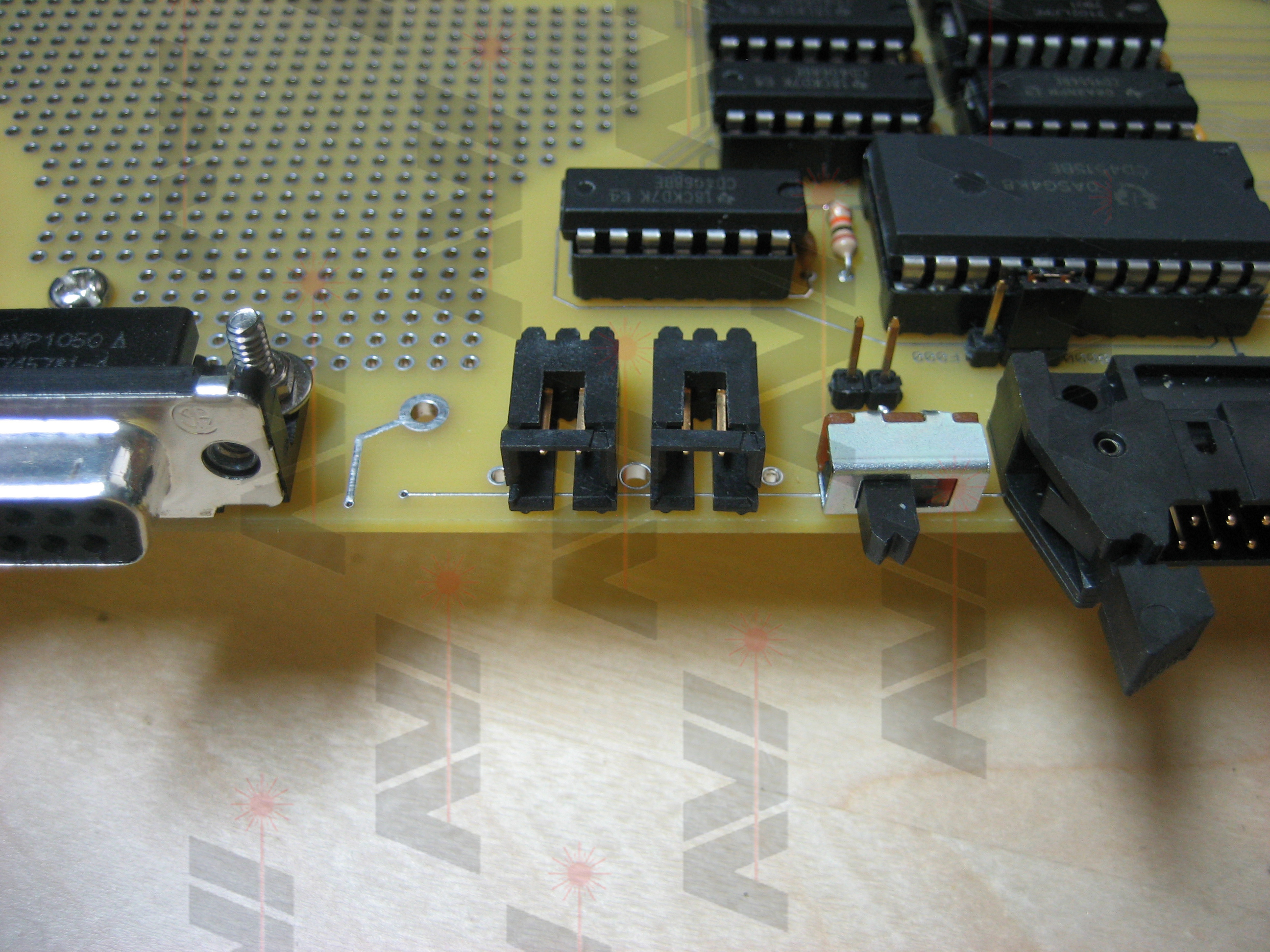
I finally got the board to switch between VIP and VIP II modes with a simple three position shunt jumper and power cycle. Here is a picture of the blue mode select jumper:
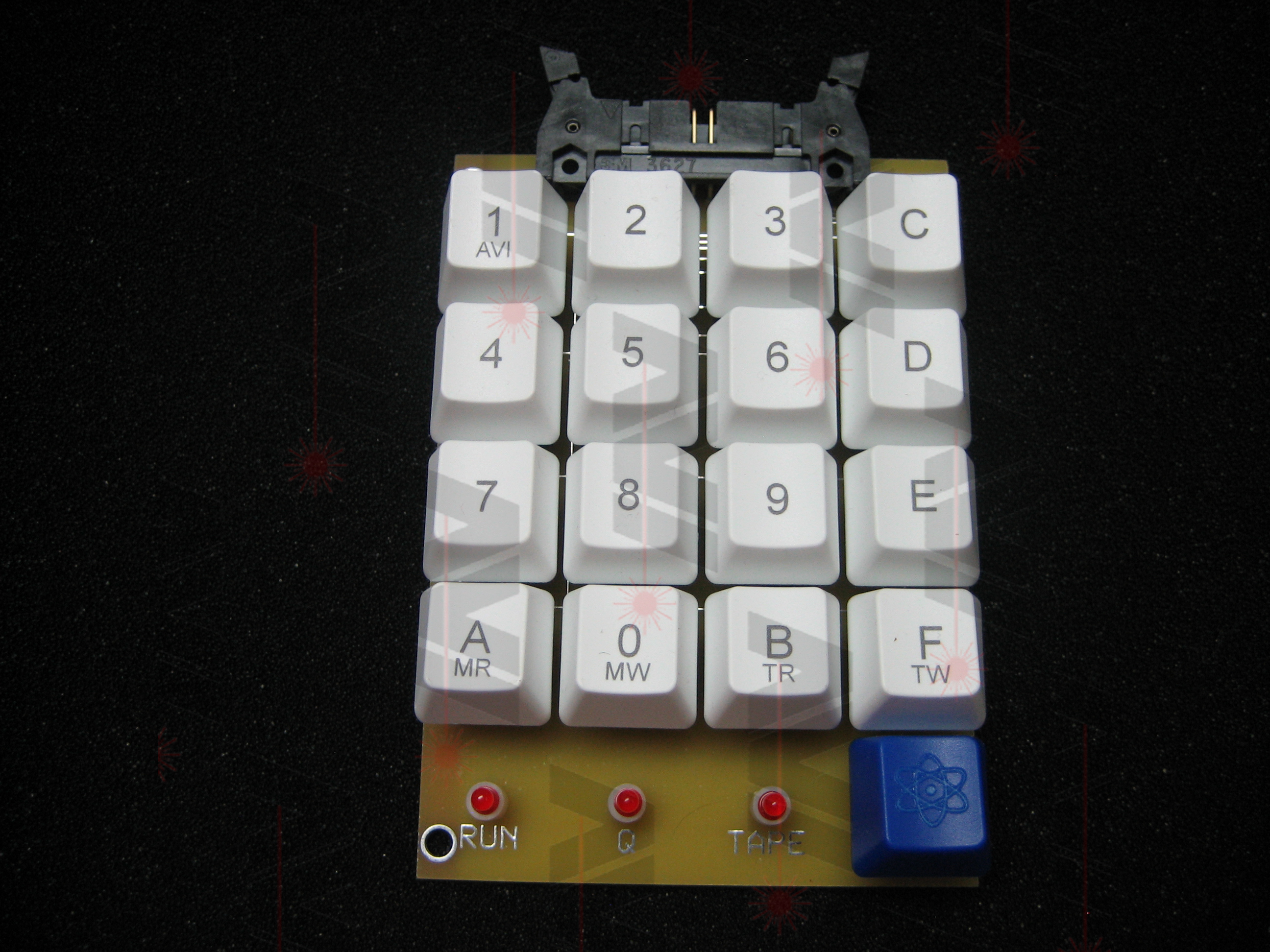
KEYBOARD AND KEYPAD
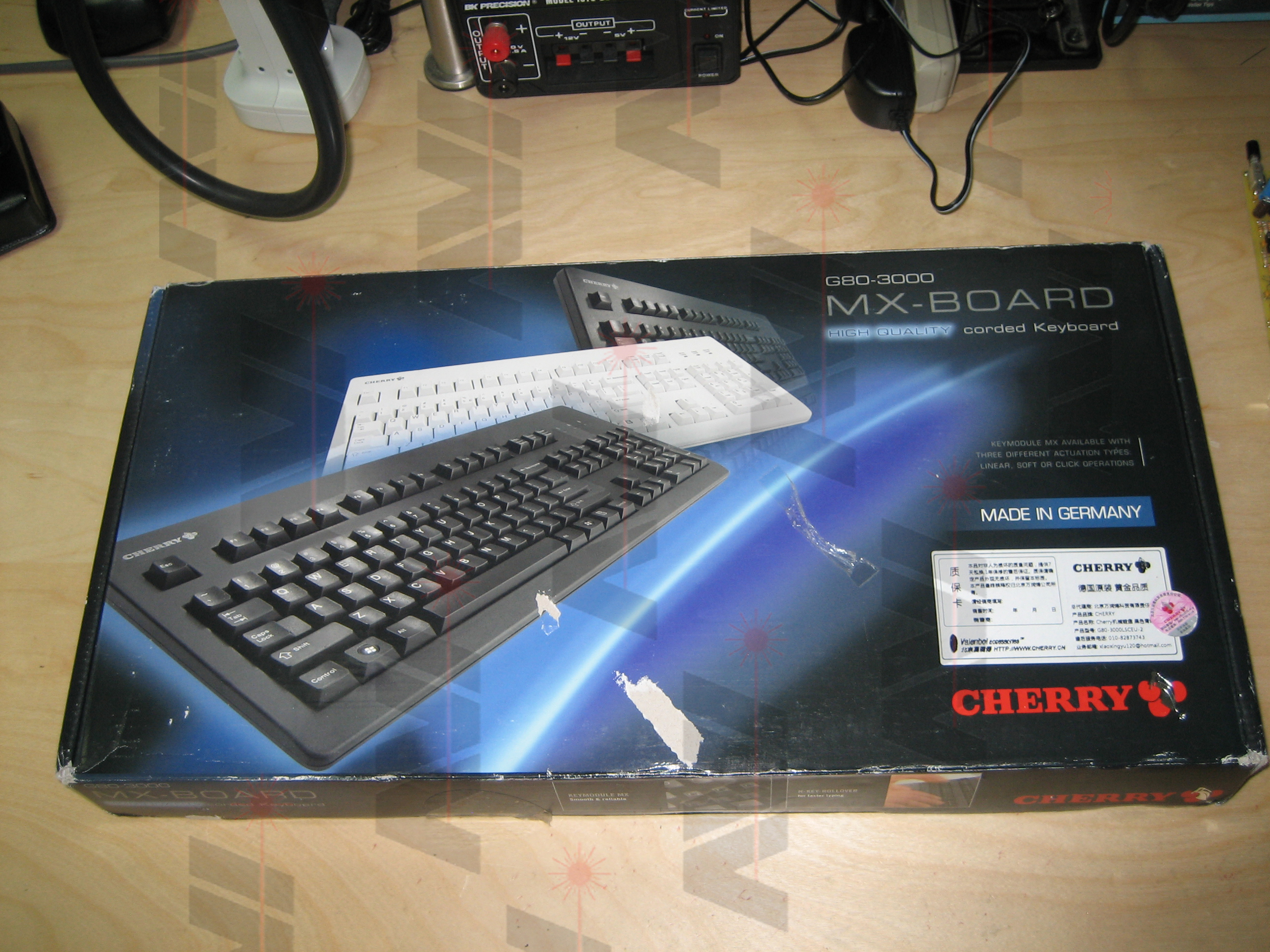
Since a membrane keyboard was out, due to cost, I looked into building a normal keyboard for the VIP II. I found there is an entire segment of the PC gamer world building their own custom keyboards. In fact a website, geekhack.org/, was really helpful. There I found I could have custom keycaps made, but mostly only for Cherry MX switches.
Cherry MX switches are available with different features and are about $5 from normal sources. I decided to use Cherry MX BLUE switches because of the tactile feel and 'click' sound they make, like the original IBM PC keyboards.
I ordered a Cherry 3000 series keyboard off eBay:
I then removed one of the key switches. I designed a PCB footprint for the switch. I then removed the rest of the switches from the Cherry keyboard.
I took measurements for the keys that have stabilizers (space, shift and return) and made a new set of footprints for them.
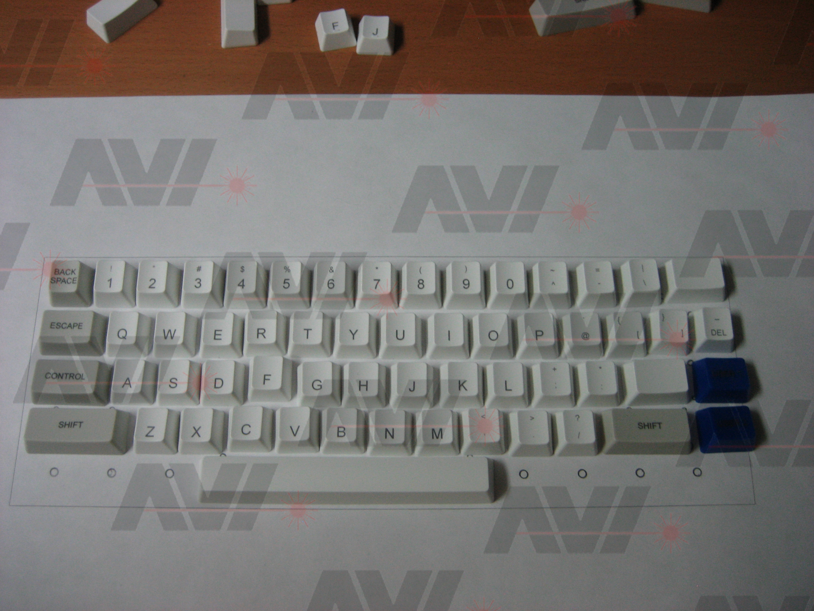
I found the wasdkeyboards.com website and started designing a set of keycaps for the keyboard using their custom keyboard designer. I started laying the keys out trying to match the VIP II keyboard in the brochure.The RCA keyboard has non-standard key sizes for some keys. I had use row 1 key caps for the 'Return' and 'Line Feed' keys.
I received the keycaps. They are laser etched and look really good. The BLUE 'STAR', 'USER 1' and 'USER 2' keys are sort of hard to read.
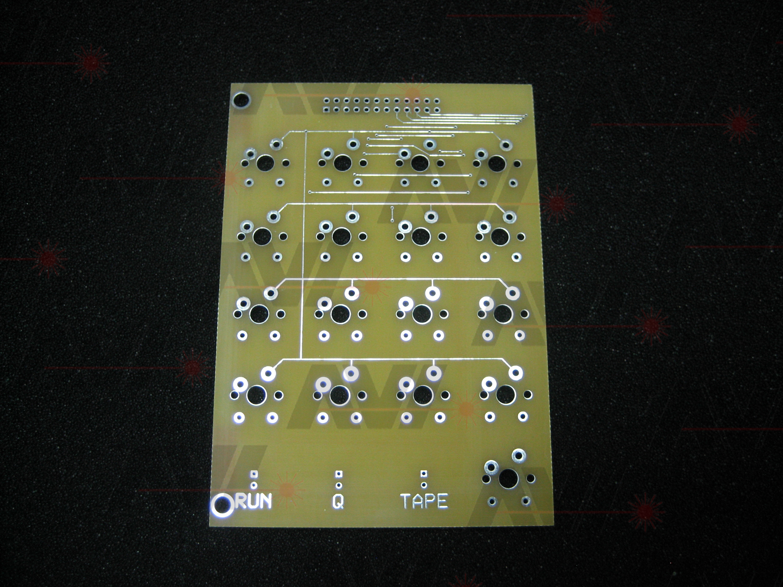
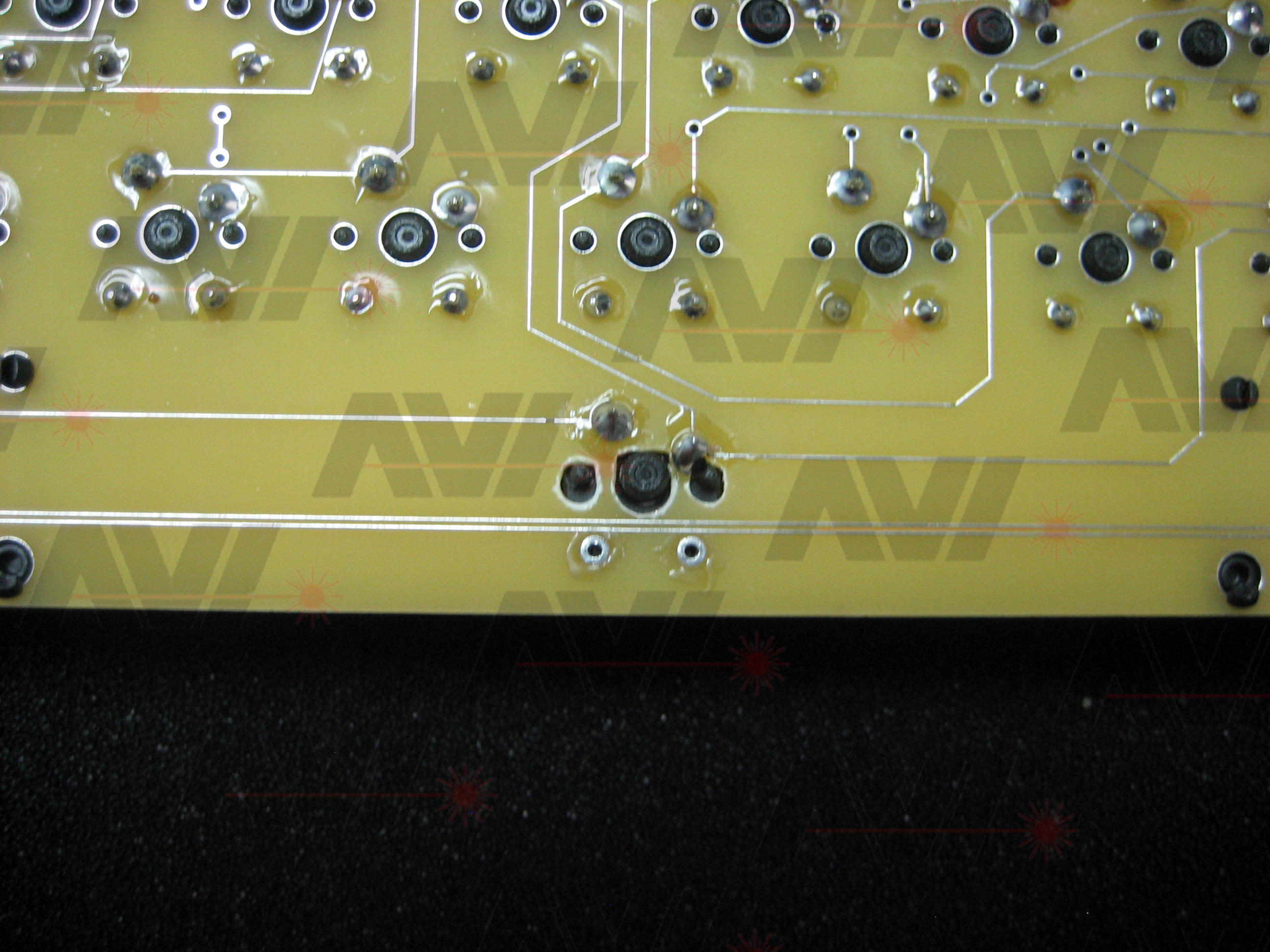
I designed a PCB for the VIP II keyboard. The PCB supplier I use has a maximum width of 14" so I designed the keyboard and keypad separately.
Here are some photos:
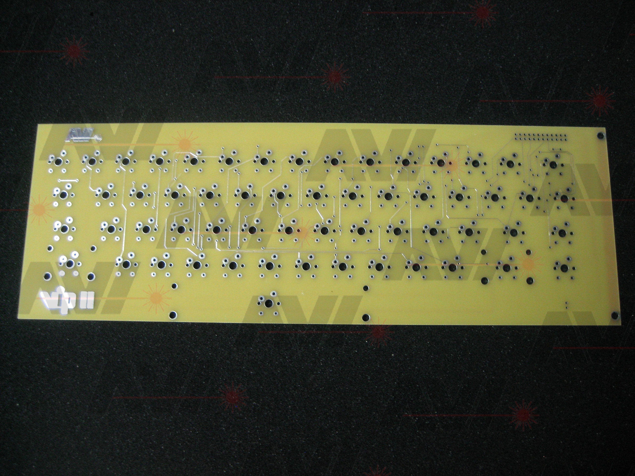
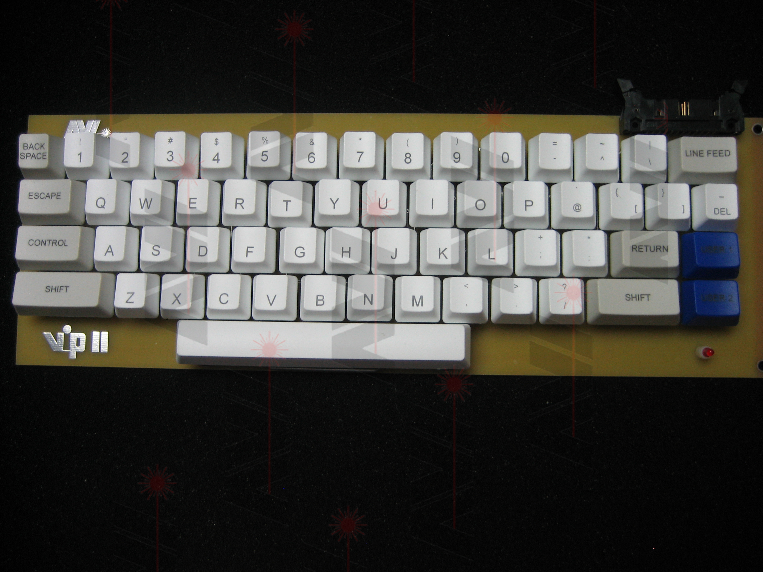
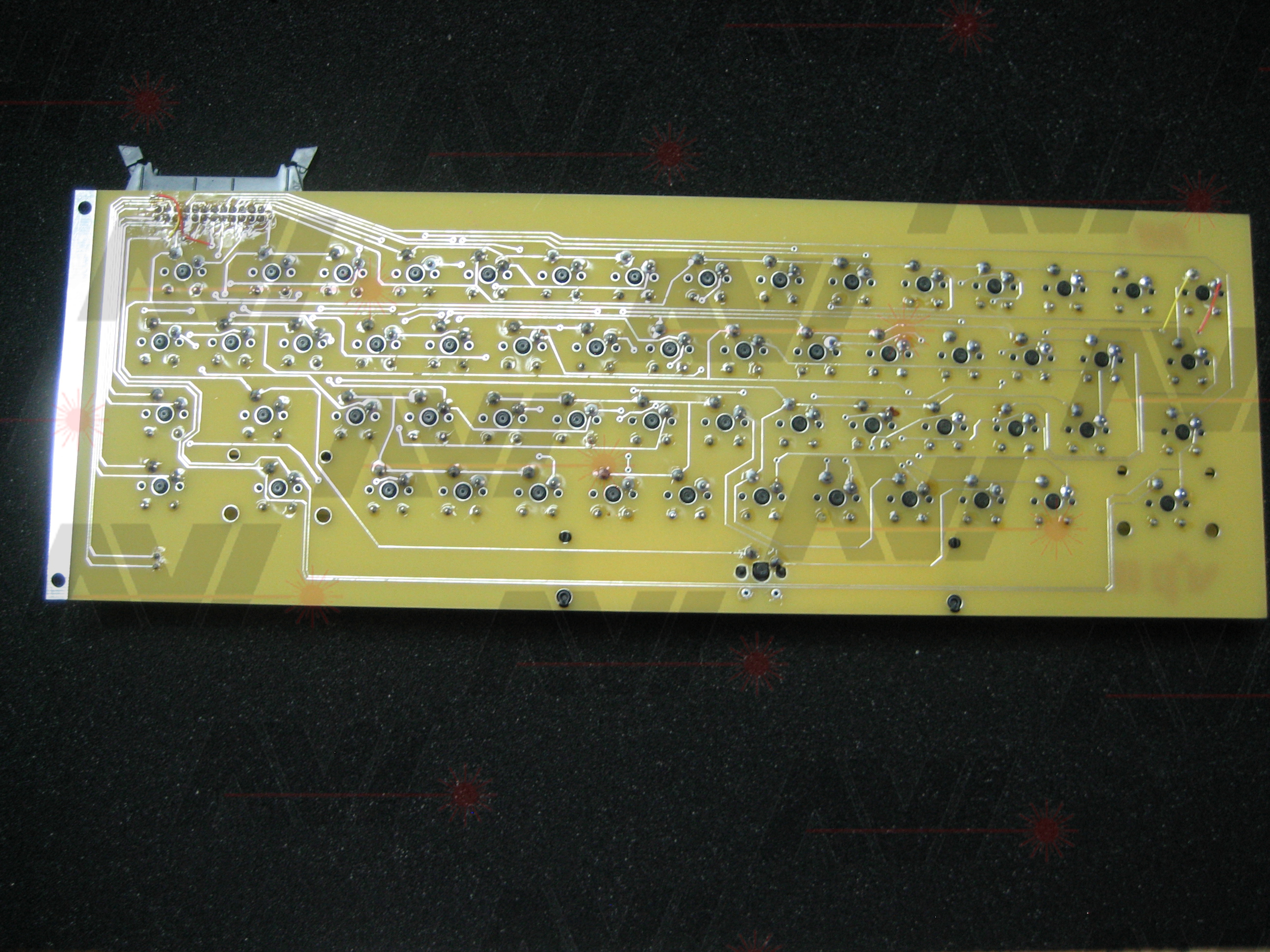
I built the two boards. The keypad went together fine.
The space bar on the keyboard binds. Turns out I had the switch itself too close to the front of the board for the stabilized keys. I had to ream the holes on the PCB towards the back of the board by a few mm. The space bar now works fine.
I decided not to do the modification for the shift keys.
Here are the finished keyboard and keypad. I think they came out pretty good for my first keyboard design.
KEYBOARD CONNECTORS
When I designed the main PCB I didn't have a connector in mind for the keyboard and keypad, so I just brought the connections out to a row of holes. I built a pretty shaky set of adapters for the keyboard and keypad, but they work.
So far the only problems I have with the keyboard is with the delete and back space keys. I described how these are not encoded correctly using the CDP1871.
The delete key unshifted produces an underscore, not a delete. The delete key is supposed to cancel what has been typed so far in FPB and drop to a new line with no other action.
I have decided that I am going to have a new keycap made and just leave the delete key the way it is.
The backspace is a bigger problem in that there is no way to back space over a typed character. The backspace is built into the encoder as CTRL-H. This issues a 08h and works as it should. I don't see a way to add a dedicated backspace key.
THE DARK SIDE
I have decided to go to the dark side and add a small PIC micro to handle a couple of things: the 'STAR' button, the backspace key and the switching of VIP/VIP II mode.
Here is what I have decided in regards to handling the 'STAR' key and VIP mode:
- When powering up:
- - If the star button is NOT pressed, system is a VIP II. Starts up running FPB. You are at the 'C/W?' screen.
- - If the star button IS pressed, the system is a VIP. System starts up in RESET.
- In either case after booting, the 'STAR' button is the reset switch. The 'RUN' LED indicates the current state.
- - In VIP mode: Toggles between RUN/RESET after a debouncing time of ~50ms. To enter the VIP monitor, while in reset, hold the 'C' key and press the 'STAR' key
- - In VIP II mode: Toggles from RUN to RESET after a 2 second delay. Toggles from RESET to RUN after a debouncing time of ~50ms.
If the 'STAR' key is accidentally pressed, just hold it for 4 seconds and the press is ignored. The 'RUN' LED flashes to indicate that it is okay to release the 'STAR' button.
Here is what I have decided to handle the 'backspace' key. I am going to bring the contacts of the backspace key to the PIC chip. When pressed, the PIC will force the 'CTRL' key and then after a short delay, 'press' the 'H' on the CDP1871. This will force the Backspace command.
I wrote a small program for the PIC that handles the 'STAR' button.
I built the PIC circuit on one of the unused address decoder boards for testing.
After testing and programming, I added the PIC circuit to the main board with a single pushbutton to act as the 'STAR' button. I then added the sound circuit and amplifier to the main board. Both work fine.
1K OF RAM FOR COLOR
I revisited the color RAM issue and redesigned it using more readily available 2102L ram chips. The only other separate I/O RAM I could find was from Cypress and the smallest they make is 4K in an SOJ package.
I built the RAM circuit on a small perfboard. I removed the CDP1822 from the color board I built for the original VIP and inserted this circuit. To save on wiring, I just stacked the chips and turned up the data pins.
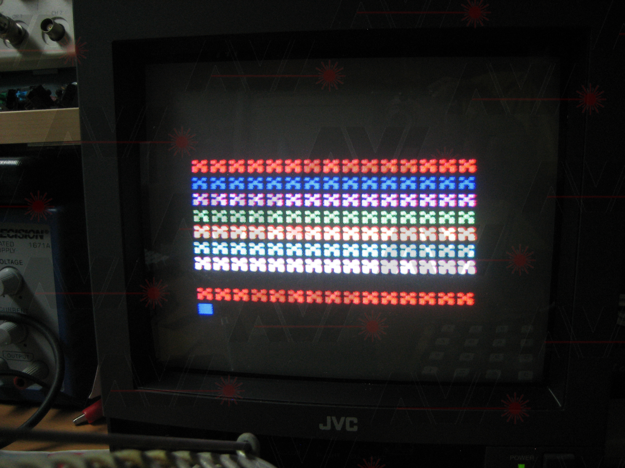
Tested with FPB and it works. I can issue a 'color (1,0,0,8,128)' and the entire screen fills from top to bottom. No mirroring! I didn't need to modify FPB to make this work, it was already coded for 1K of color memory as I thought from looking at the 'CLC' function.
THE FINAL BOARD
Designed a new PCB that contains everything I want the final board to have. I decided not to build the UART and USB circuit onto the final board.
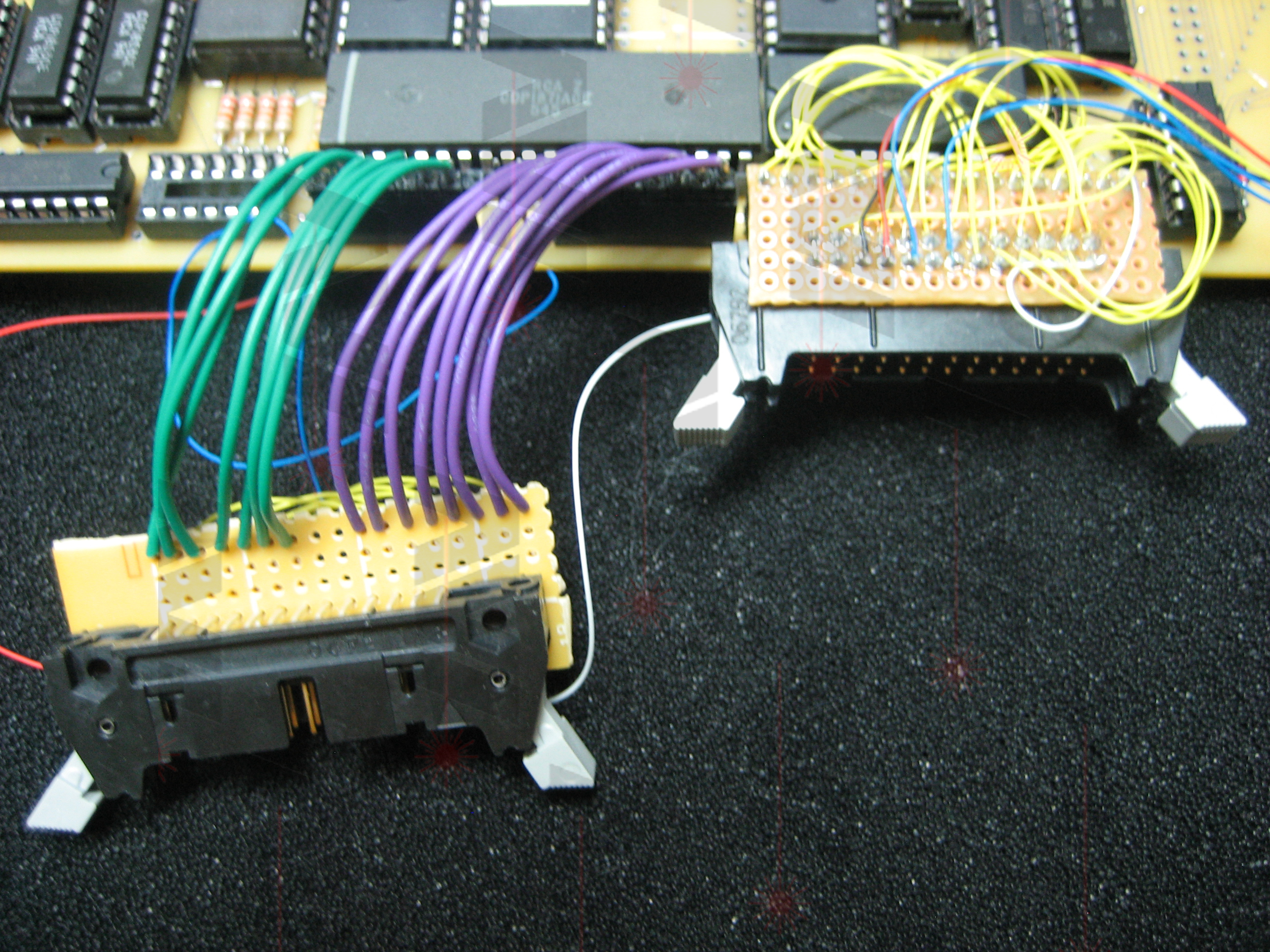
The FPB manual suggests a circuit that will operate the 'remote' jack on two different tape decks, one for write and one for read. I have added a circuit that does this to the final board.
Here is the final board I designed:
I built the new pcb. Here it is fully assembled:
I found two issues. The first was that I had the '/CLEAR' signal split into two different traces due to a typo on the schematic. I had forgot the '/' in front of the 'CLEAR' on a couple of connections. They were labeled independently on the schematic leading me to keep them separated on the PCB. A small rework jumper fixed this.
I also added a 1N4004 diode to the power circuit. Usually this isn't a problem and protects against reverse polarity. The problem is that I designed the circuit to use a direct regulated +5 volts in, and not a regulator circuit using a 9 to 12 Volt input. I added the diode to the circuit, not thinking about the voltage drop of .7 volts. I noticed this because my input voltage was 5.00v and the reading at pin 40 of the 1802 was 4.33v. A drop of .67 volts.
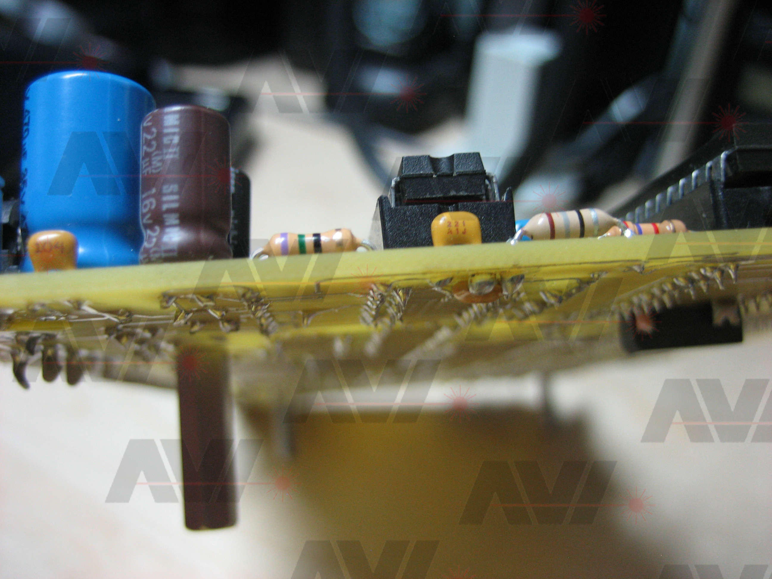
Also, I didn't have a 110pf cap so I wired 2 220uf in series to make the correct value.
I modified the keyboard to repurpose one of the LED leads for the backspace key. I put it to 5v. I cut both traces to the backspace key and wired one to 5v and the other to the now free LED pin. I reprogrammed the PIC chip to handle the new wiring of the Power LED and the backspace key. The backspace key now works as it should.
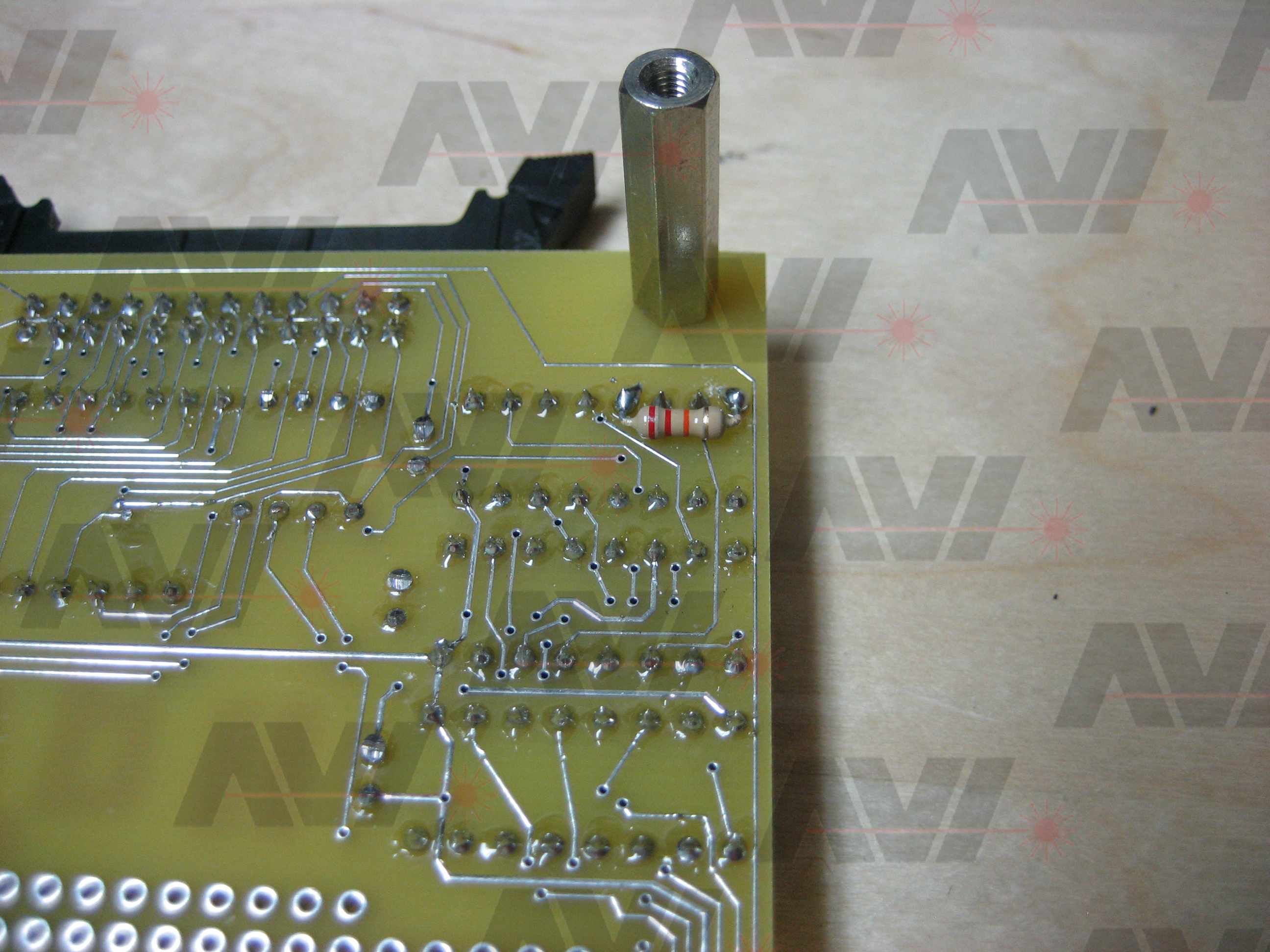
I noticed the cassette 'remote' relays are sometimes active at power up. This would cause the tape decks to start. I added a pull down resistor to the latch, now the relays behave.
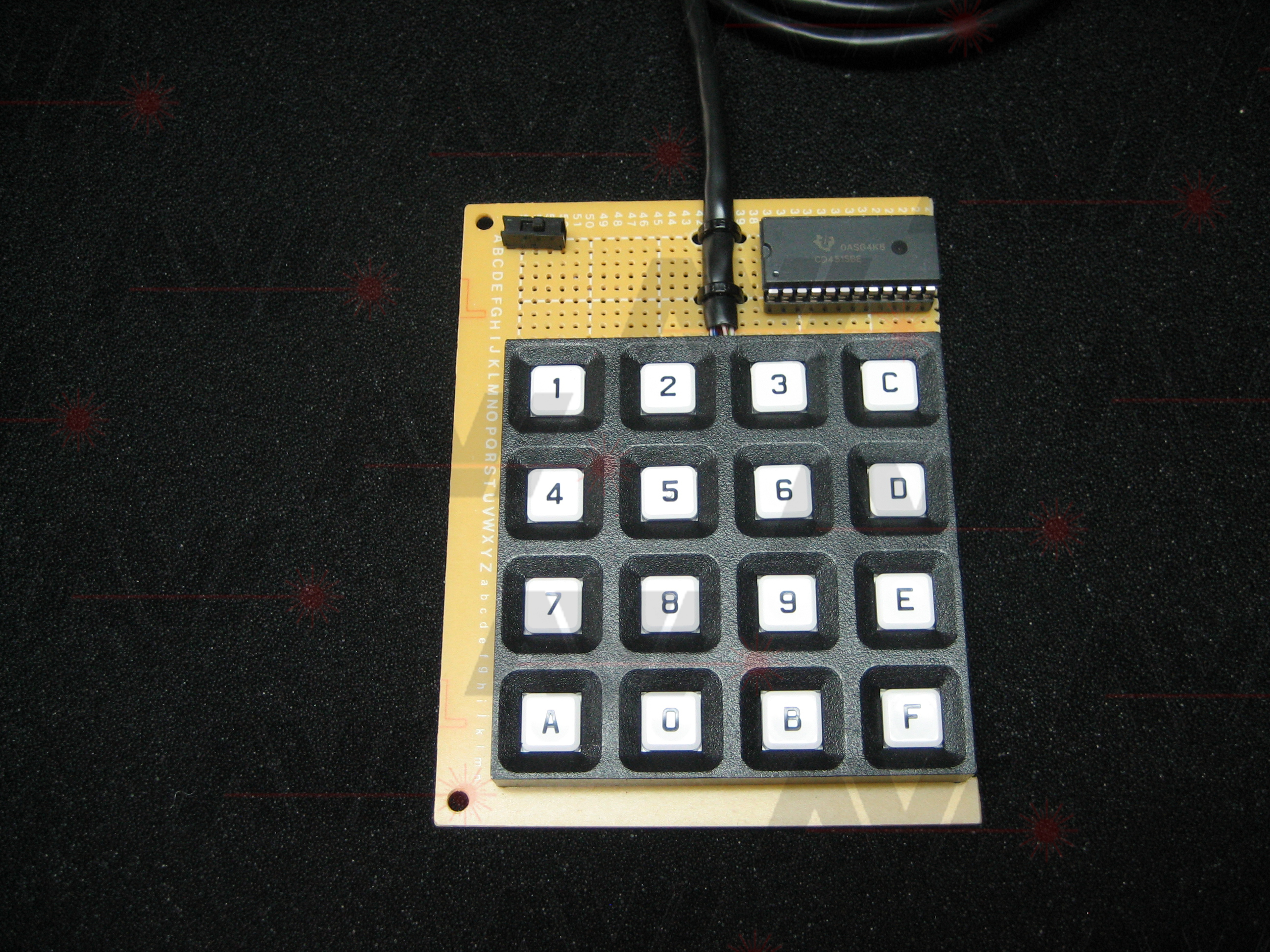
To test the game port, I built an additional game keypad for testing. I added a switch to it so I could test both 'Player 1' and 'Player 2'.
The VIP II brochure indicates that a 25 pin dual-readout card edge is available for expansion. That sounds like fingers to me. I looked for a 50 pin connector for card edge fingers and could not find one. I decided to go with a 50 pin IDC connector. I did make a change though. The brochure indicates that the 'USER' keys are on the expansion port. I brought them out to a pair of separate connectors.
This way I could have more of the 1802 signals on the expansion connector. Here is the pinout I went with:
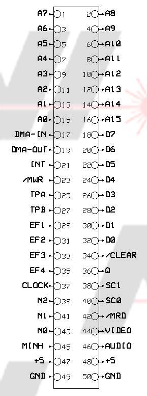
The VIP II brochure also indicates that the lines on the expansion are buffered. I decided to not add that circuitry since I have no plans to expand this board.
SUMMARY
Well that's it. I believe I have done it. I have built an 1802 based computer that does all the things listed on the specification page of the VIP II brochure. I am happy with the results. I'm not sure of what I will do with it now.
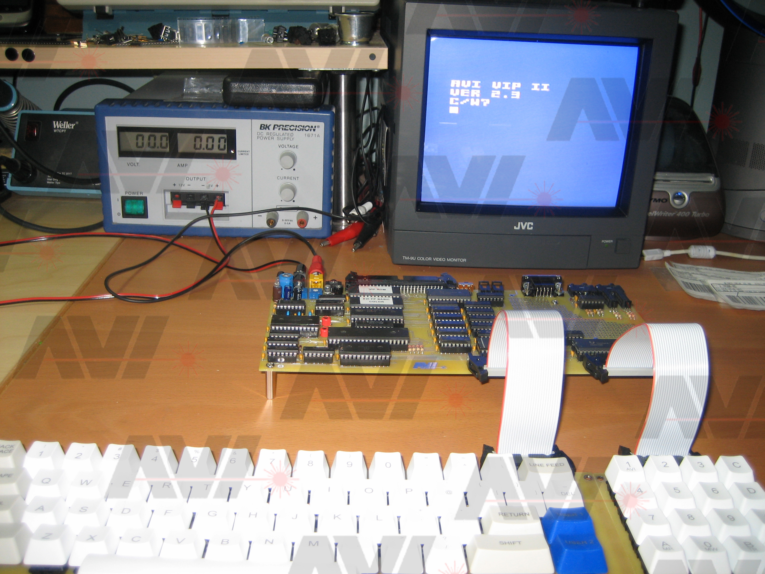
Since I modified the bootloader in the EEPROM, I bumped the software version to 2.3. While I was in the EEPROM image, I changed the splash message from: 'VP-701 BASIC' to 'AVI VIP II'
Like I said at the beginning of this project, 'Simply put, I had to have it'. Now I do.
Here are some photos of the final board and some screen images of it running.
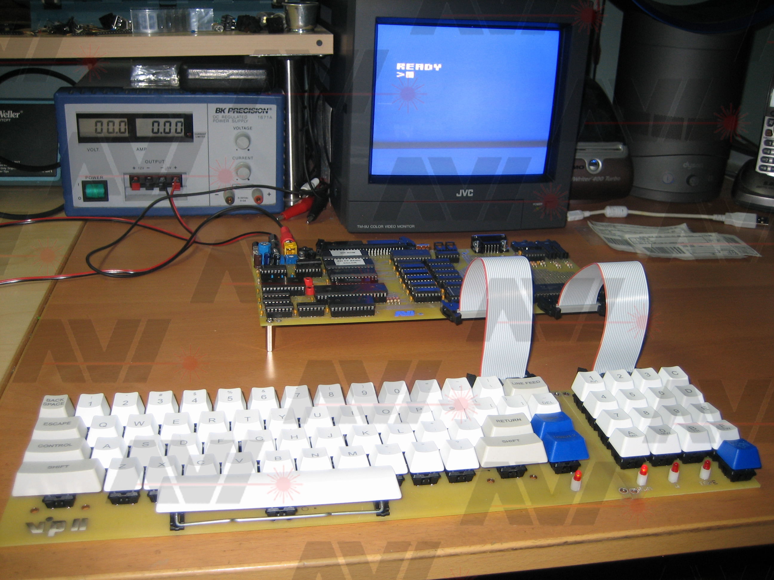
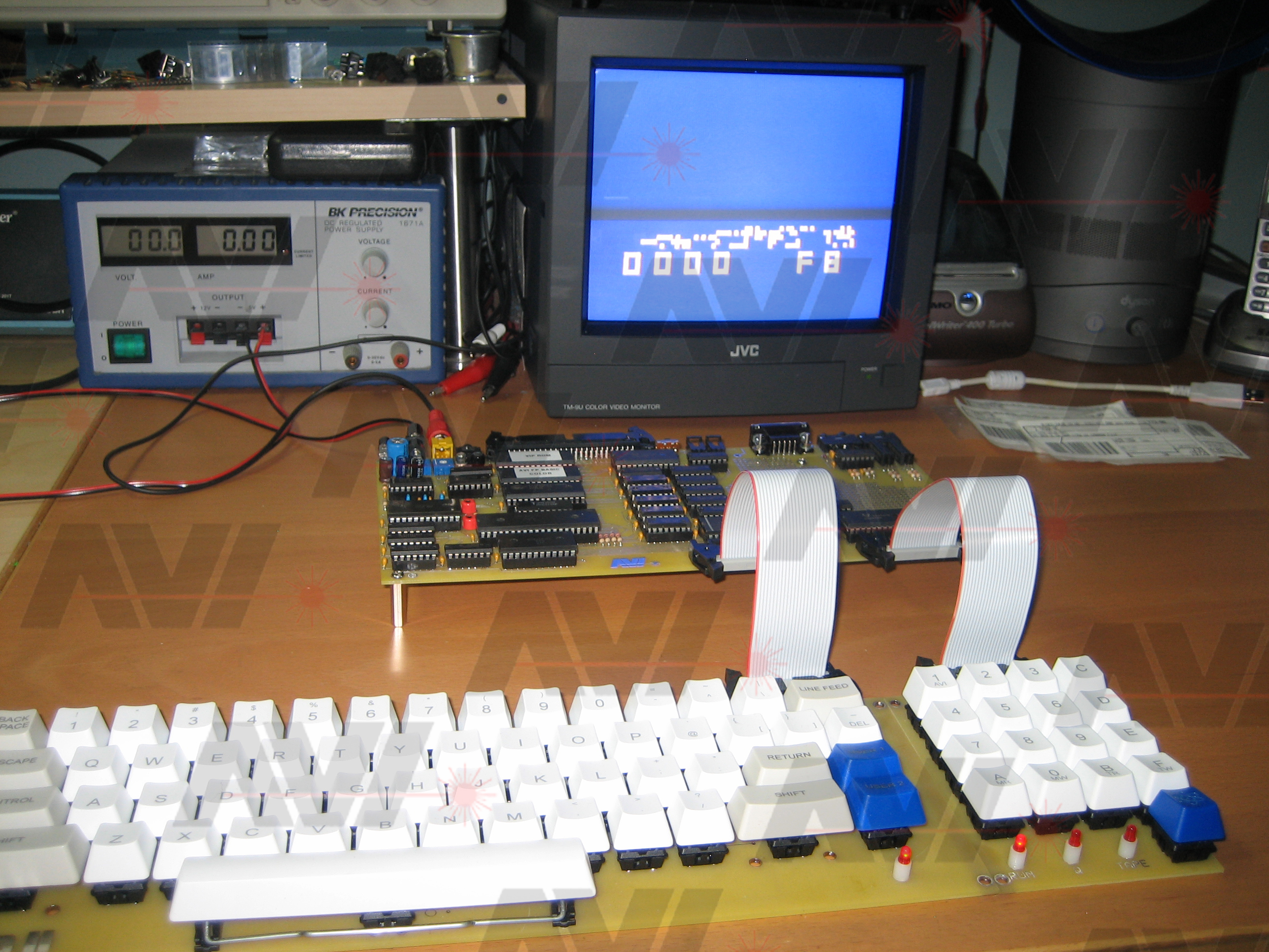
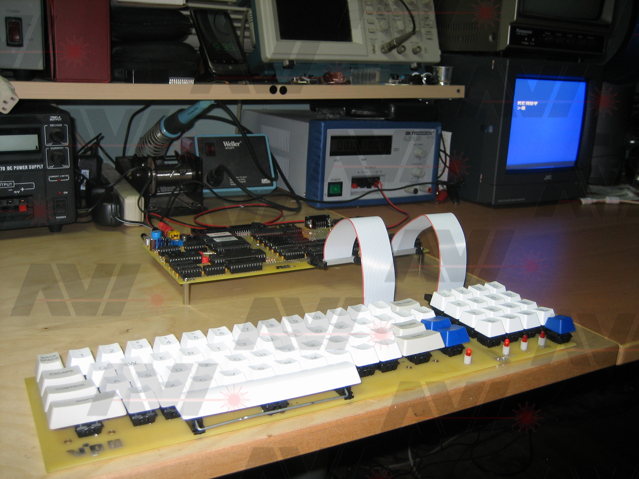
Here are a few short videos of operation. The interference and black lines on the screen are an artifact of directly filming the monitor.
How the screen updates with 256 Bytes of RAM:
And here is what it looks like with 1K of RAM:
Changing the background color:
Plotting a sine wave with Floating Point Basic:
Reading bytes of memory starting at address 0000h, and sending them to the sound chip. Video starts in VIP 1 mode then steps through the short program's code. System is reset and run for a short time. As a byte is read, it is 'played' through the sound circuit. The system is reset and run in VIP 1 mode. The power switch is pressed turning the system off, then pressed again turning the system back on. The 'STAR' key was not held allowing the system to come up in VIP II mode.
Thank you for reading this. I hope you found it interesting.
ED
Please feel free to contact me at the e-mail address in this image: